Advertisement
OPERA
OPERA T T T T T ORS'
OPERA
OPERA
OPERA
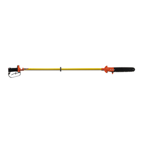
LR-88.5
HYDRAULIC
LONG REACH
CHAINSAW
ORS'
ORS'
ORS' GUIDE
ORS'
/
LR-75
For cutting and trimming of limbs and
branches from the ground or an aerial bucket
that a standard chainsaw could not reach.
DISTRIBUTED BY
LR Manual 05-08
GUIDE
GUIDE
GUIDE
GUIDE
/
LR-62.5
WARNING
All information found in this guide
must be read and understood before
use or testing of this tool. Failure
to read and understand these warnings
and safe handling instructions could result
in severe personal injury and or death.
1
Advertisement
Table of Contents

Summary of Contents for Reliable Equipment LR 88.5
- Page 1 OPERA OPERA T T T T T ORS’ OPERA ORS’ ORS’ GUIDE GUIDE ORS’ GUIDE GUIDE OPERA OPERA ORS’ GUIDE LR-88.5 LR-75 LR-62.5 HYDRAULIC LONG REACH CHAINSAW For cutting and trimming of limbs and branches from the ground or an aerial bucket that a standard chainsaw could not reach.
-
Page 2: Table Of Contents
TABLE OF CONTENTS Saw Description ......2 PARTS LISTS Registration ........2 Major Components ..... 15 Safety Instructions ....3-6 Head, motor side ......16 Head, chain side ......17 SPECIFICATIONS Handle ......... 18 General .......... 7 REPAIR INSTRUCTIONS Connections and Hoses ....8 Disassembly ...... - Page 3 BEFORE USING THIS CHAINSAW, READ THE WARNINGS and the recommended practices described in this manual. Failure by the operator to read and fully underst and these warnings will leave this person unqualified to use and operate this tool. Property damage, severe personal injury , WARNING and/or death could result by not following these warnings.
- Page 4 Safety DO NOT attempt to make any changes to any of the component parts or accessories when connected to the power source. WARNING DO NOT adjust, inspect, or clean tool while the tool is connected to the power source. The tool could accidentally start up and cause serious injury.
-
Page 5: General Safety
Burn Hazard Saw body, blade, bar as well as other component s will be hot during and after use. Use care when handling this tool. Hot surfaces may cause serious burns. Failure to observe this WARNING warning may result in serious personal injury . Electrical Shock Hazard Use only certified nonconductive hoses and fittings. - Page 6 Burn Hazard Do Not connect or disconnect tool, hoses or fittings while power source is running or while hydraulic fluid is hot. Hot hydraulic fluid may cause serious burns. WARNING Failure to observe this warning could result in serious injury . Safe Operation &...
- Page 7 TOOL SPECIFICATIONS Overall Length ............62.5 in., 75 in., 88.5 in. Handle Width ..............7.5 in. (19.05 cm) Motor Width ................. 5 in. (11.43 cm) Weight................9.5 lbs. (4.22 kg) Cutting Chain @ 8GPM (30 ipm) ... 4,200 fpm/min (1,280 m/min) Pitch ................
-
Page 8: Hoses And Fittings
HOSES AND FITTINGS There exists the potential for shock in using anything other than certified nonconductive hoses and hydraulic oil with dielectric properties, when using system components near WARNING energized electrical lines. Failure to recognize these conditions could cause electrocution. Hoses and fittings used with this tool must comply with S.A.E. -
Page 9: Operation Of Saw
PRE-OPERATION OF SAW WARNING! DO NOT connect hoses or fittings to this chainsaw before completing all the following instructions. Before attempting to run or use the saw, check all connections, including hoses, couplings, chain tension, cleanliness of the fiberglass extension, trigger latch, freely moving trigger, and the condition of the rubber behind the trigger. -
Page 10: Safety Instructions
OPERATION Hold the fiberglass tube extension in one hand and the handle in the other hand. After positioning the saw in the cutting area, move the trigger safety latch to a forward position, allowing the trigger to be depressed. Depress the trigger slowly and allow the chain to start rotating. - Page 11 MAINTENANCE The service schedule should be followed as closely as possible. The life, reliability, and safety of the tool is dependent on maintenance and will help the tool to remain productive for a much longer period. DAILY MAINTENANCE CLEAN: All surfaces including handle, trigger, trigger safety latch, fittings, hoses, motor housing, and especially the fiberglass extension tube.
- Page 12 SERVICE Automatic Chain Oiler: The automatic chain oiler is designed to continuously lubricate the chain and the guide bar while the chainsaw is running. This lubrication is an important factor in minimizing wear and tear on components as is commonly found in chainsaws. By utilizing the fluid from the supply circuit and sending the fluid through a metering valve, the fluid is then directed to the chain and guide in the quantity required.
- Page 13 Saw Chain Tension: Tension checking and adjusting must be done frequently before start and during cutting operations. The chain must be set to the proper tension in order for the saw to function properly. If the chain is too loose, the chain can jump the track of the guide bar, probably causing damage to the bar and associated components.
-
Page 14: Troubleshooting
TROUBLE SHOOTING Will not run Low hydraulic fluid ............Check fluid level Incorrect viscosity ............. Use recommended fluid Tool damaged ..............Disassemble and replace damaged parts Hoses incorrectly connected ..........Switch hoses Dirt in tool ................. Disassemble, clean and repair Loose parts in tool ............ - Page 15 MAJOR COMPONENTS PARTS LIST 13 Label Set FIGURE 4 Part No Description Qty. 13447 O-Ring, Internal 13415 Front Tube Support Outer Tube 13276S For Model LR-88.5 13277S For Model LR-75 13278S For Model LR-62.5 13422 Grommet Return Tube 13251 For Model LR-88.5 13452 For Model LR-75 13453S...
-
Page 16: Head, Motor Side
HEAD (MOTOR SIDE) FIGURE 5 Item Part No. Description Qty. 13403CM Complete Motor Assembly 13403 Motor Body 13427 Woodruff Key 13406 Drive Shaft 13413 O-Ring (Oiler) 13412 Lube Plug (Oiler) 13434 Snap Ring, Bearing Ret. 13411 Sealed Bearing 13435 Needle Bearing 13426 11 Tooth Gear 13407... -
Page 17: Head, Chain Side
HEAD (CHAIN SIDE) PARTS LIST FIGURE 6 Item Part No. Description Qty. 13403CM Complete Motor Assembly 13453 Chain 13431 Chain Bar 13419 Chain Adjuster 13455 Adjusting Screw and Retainer 13456 Assembly Screws 13449 Flat Washer 13418 Cover 13409 Jam Nut 13433 Flat Washer 13408... -
Page 18: Handle
HANDLE PARTS LIST FIGURE 7 Item Part No. Description Qty. 13402CH COMPLETE HANDLE ASSEMBLY 13421 OC/CC Knob 13423 Snap Ring, Spool 13424 Spool Retainer Washer 13414 O-Ring, Back of Spool 13420 Spool 13402 Handle Body 13428 Spool Spring 13448 Screw, 1/4-20 x 3/4 13445 Spring Pin 11 *... -
Page 19: Disassembly
DISASSEMBLY CHAIN AND MOTOR ASSEMBLY Before any disassembly, disconnect hoses from the Chainsaw! Any residual pressure within the unit can and will spray at high velocity, injuring the person doing the disassembly. Hot or pressurized hydraulic fluid will cause serious injury to the body! Accidental movement of the chain can cause serious injury, WARNING dismemberment of a hand, finger or any other part of the body. - Page 20 VALVE/HANDLE DISASSEMBLY Refer to Figure 7, Page 18 Remove the three button head screws (13) holding the trigger guard to the valve body. Remove one snap ring (15) from the pin (14), holding the trigger to the valve body, and remove pin. Before removing the control knob (1), mark the relative position to the spool (5).
- Page 21 ASSEMBLE TUBES See Figure 4, Page 15 Tie the two inner tubes together with the three O-rings (7) twisted in a figure 8 configuration. The pressure tube (6) is marked with blue ink on each end. The return tube (5) has no marking. As shown in Fig. 4, the pressure tube closest to the bottom of the page.
-
Page 22: Product Update
6 Re-assemble and adjust bar and chain as needed. All future saw orders will feature a revised adjusting screw (B) with rubber lock-ring as well as staking. (Shown at right ) CONTACT RELIABLE EQUIPMENT WITH ANY QUESTIONS REGARDING THIS UPDA TE. - Page 23 PRODUCT UPD December 15 , 2004 RELIABLE EQUIPMENT is committed to continued customer satisfaction. As a result of this effort, product modifications and updates are made, to increase usability, enhance safety, or reduce repair cost and down time. All new Long Reach Saws beginning with Serial # 4234 will feature a modified trigger assembly.
-
Page 25: Parts Order Form
P P P P P ARTS ORDER FORM ARTS ORDER FORM ARTS ORDER FORM ARTS ORDER FORM ARTS ORDER FORM LONG REACH SAW LR-SERIES Major Components Handle Head Assembly Motor Assembly... - Page 26 92 Steamwhistle Drive Ivyland, PA 18974 Phone: 800-966-3530 Fax: 215-357-9193 Visit us on the web at www.Reliable-Equip.com...
Need help?
Do you have a question about the LR 88.5 and is the answer not in the manual?
Questions and answers