Table of Contents
Advertisement
Advertisement
Table of Contents

Related Manuals for Barnstead FB1310M

Summary of Contents for Barnstead FB1310M
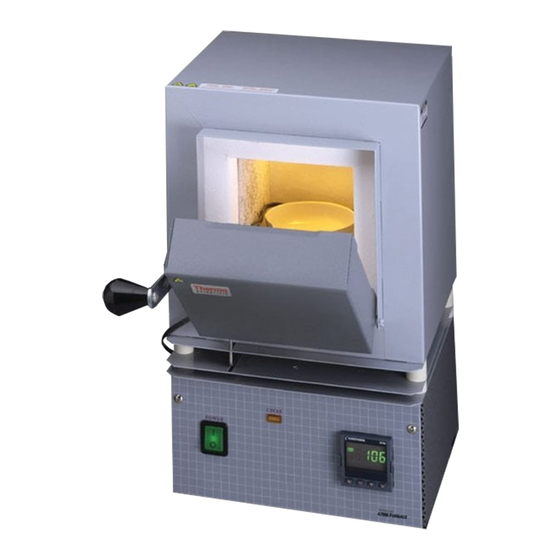
- Page 1 ARNSTEAD HERMOLYNE ORPORATION Type FB1300 & FB1400 Furnaces OPERATION AND REPAIR MANUAL AND PARTS LIST SERIES 1256 & 1257 Model Numbers FB1310M, FB1310M-26, FB1314M, FB1315M, FB1318M,FB1310M-33 FB1410M, FB1410M-26, FB1414M, FB1415M, FB1418M, FB1410M-33 LT1256X1 • 8/27/01 Serial Number...
-
Page 2: Table Of Contents
Table of Contents Safety Information ..............................3 Important Information............................3 Warnings ..............................4 Introduction................................5 Intended Use ..............................5 General Usage..............................5 Principles of Operation ..........................5 General Specifications ............................6 Declaration of Conformity ..........................7 Unpacking ................................8 Installation ................................9 Site Selection..............................9 Electrical Connections..........................9 Operation ................................10 Power Switch..............................10 Cycle Light..............................10 Door Safety Switch ............................10 Single Setpoint Controller ..........................10 Basic Operation ............................11... -
Page 3: Safety Information
Safety Information Alert Signals Important Information This manual contains important operating and safety information. You must carefully read and understand the contents of this manual prior to Warning the use of this equipment. Warnings alert you to a possibility of personal injury. Your Thermolyne FB1300 Model or FB1400 Model Furnace has been designed with function, reliability, and safety in mind. - Page 4 Refer to the appropriate Material Safety Data Sheets (MSDS) for information regarding proper handling and recommended protective equipment. For addi- tional MSDS copies, or additional information concerning the handling of refractory ceramic products, please contact the Customer Service Department at Barnstead|Thermolyne Corporation at 1-800-553-0039.
-
Page 5: Introduction
Introduction Intended Use The FB1300 Model and FB1400 Model fur- naces are general purpose laboratory and heat treating furnaces. For optimum element life, observe the following temperature ranges: 100°C (212°F) to 982°C (1800°F) for continuous use, or from 982°C (1800°F) to 1100°C (2012°F) for intermittent use. -
Page 6: General Specifications
Overall : 7.9” W x 13.8” H x 8.5” D (20.0 x 34.9 x 21.6 cm) Weight: 15.7 lb. (7.1 kg) Electrical Ratings: Model # Volts Amps Watts Phase Frequency FB1310M 220-240 1060 50/60 FB1310M-26 220-240 1060 50/60 FB1310M-33 220-240... -
Page 7: Declaration Of Conformity
ENERAL PECIFICATIONS Declaration of Conformity Barnstead|Thermolyne hereby declares under its sole responsibility that this product conforms with the techni- cal requirements of the following standards (-33 models only): EMC: EN 50081-1 Generic Emission Standard; EN 50082-1 Generic Immunity Standard. Safety: EN 1010-1-92 Safety requirements for... -
Page 8: Unpacking
Unpacking 1. Visually check for any physical damage to the shipping container. 2. Inspect the equipment surfaces that are adjacent to any damaged area. 3. Open the furnace door and remove the packing material from inside the furnace chamber. 4. Vacuum the chamber prior to use to remove the insulation dust due to shipment. -
Page 9: Installation
The electrical ratings are located on the spec- controller. ification plate on the back of the furnace. Consult Barnstead/Thermolyne if your electri- cal service is different than those listed on the Caution specification plate. Be sure the front power... -
Page 10: Operation
Operation, All Modes Power Switch Warning Both the ON/OFF power switch and the digital To avoid personal injury do not use display will illuminate when power is switched in the presence of flammable or ON. The furnace will begin to heat to the con- combustible chemicals;... -
Page 11: Basic Operation
Single Setpoint Controller Temperature The single setpoint model furnace controller Output 2 Output 1 Display is a single setpoint controller which provides a single digital display to indicate the current chamber temperature or setpoint temperature. This temperature controller features sensor break protection and self-tuning capability. -
Page 12: To View The Display Units
INGLE ETPOINT CONTROLLER desired setpoint value is displayed and then release the button. A few seconds after the button is released, the controller will accept the new value and revert to the HOME DISPLAY. To View the Display Units From the HOME DISPLAY press the SCROLL button. -
Page 13: Alarms
INGLE ETPOINT ONTROLLER Atun List tunE: One-shot autotune enable. Pid List Pb: Proportional band (in display units). ti: Integral time in seconds. td: Derivative time in seconds. ACCS List Code: Access code (Code need- ed to enter or change the other configuration parameters which are not normally accessi- ble.) Not accessable. -
Page 14: Sensor Break Protection
Use this feature the first time you use your furnace and each time you change either your setpoint or the type of load you are heating. Barnstead|Thermolyne recommends you use this feature to provide the best temperature accuracy the controller can attain. To use the tuning feature: Adjust the setpoint to your desired value. -
Page 15: Tuning
INGLE ETPOINT ONTROLLER 3. Press the SCROLL button. Display will read, “tunE.” 4. Press the UP or DOWN button to select, “on.” 5. Simultaneously press the PAGE and SCROLL buttons to return to the HOME DISPLAY. The display will alternately flash between “tunE” and the HOME DISPLAY while tuning is in progress. -
Page 16: Furnace Loading
Furnace Loading • For best results of furnace loading, use less than two-thirds of any dimension of Caution the chamber. Maintain a 3/4" clearance Do not overload your furnace between the load and the sides of the chamber or allow the load to chamber. -
Page 17: Preventive Maintenance
Before using any cleaning or from tool steel). decontamination method except those recommended The resistance wire is high-grade nickel-chromium. by Barnstead|Thermolyne, Some chemicals, notably sulphur, halogens, and users should check with cyanides, attack this wire at high temperatures, so Barnstead|Thermolyne that... -
Page 18: Troubleshooting
Troubleshooting Problem Possible Causes Corrective Action The furnace does not heat No power. Check power source and fuses or (CYCLE light does not illuminate). breakers. Defective electrical hookup. Repair electrical hookup. Thermocouple has oxidized and Replace thermocouple. opened the circuit. (Open thermocouple is indicated on the display as a temperature of 0-5 degrees). -
Page 19: Maintenance And Servicing
Maintenance and Servicing Warning Disconnect the furnace from the To Replace Heating Element power supply before servicing. 1. Set the furnace on its top. (See Figure 3). Refer servicing to qualified Remove thermocouple cover. (If personnel. equipped.) Note 2. Remove screw and clamp holding ther- Perform only maintenance mocouple, then grasp the thermocouple described in this manual. - Page 20 AINTENANCE AND ERVICING 6. Remove the back insulation block by open- ing the door and gently pushing it out. Support this insulation block while removing it, as it is quite soft and easily crumbled at the edges. 7. Remove bottom cover to obtain access to terminals.
- Page 21 AINTENANCE AND ERVICING Make the bend 90°, avoiding excessive bend- ing. (The element wires will be exposed at the corner thus formed. This will not affect its life or performance.) 13. Bend the other side of the element. 14. Place the hearth plate across the open end of the ‘’U”...
-
Page 22: To Replace Thermocouple
AINTENANCE AND ERVICING about 1-1/2" into the chamber. Make sure porcelain insulator is in place for the ther- mocouple to pass through on the steel back plate. Replace clamp and screw. (Excessive scaling, pitting, or cracks are some indications that the thermocouple may need to be replaced.) 20. -
Page 23: To Replace Insulation
AINTENANCE AND ERVICING 7. Thread the thermocouple through the hole in the base which has a nylon insulator, replace clamp and screw. 8. Bend the thermocouple sharply toward ter- minal block. 9. Secure the two yellow wires marked “+” together on the terminal block. Secure the two red wires “-”... - Page 24 AINTENANCE AND ERVICING 6. Disconnect thermocouple leads from terminal block. Remove four nuts holding control section to furnace chamber. Remove the ground nut. Remove the control section from the furnace Note chamber. Remove plates, screws, spacers Identify or mark wires discon- and nuts.
-
Page 25: To Replace Door Switches
AINTENANCE AND ERVICING 18. Thread the element leads and ceramic bushings through the bottom plate. Bend the leads so they lie close to the refractory plate and the bottom insulation block. (The easiest and safest way to do this is to press the wire flat with a stick or blunt pusher. -
Page 26: To Replace Solid State Relay
AINTENANCE AND ERVICING Warning To Replace Solid State Relay Disconnect furnace from power 1. Place furnace upside down and remove the supply before servicing. bottom cover. 2. Disconnect the wires from the solid state relay. Identify or mark the wires disconnect- ed to ensure proper placement and connec- tion when re-installing. -
Page 27: Wiring Diagram
Wiring Diagrams FB 1400 models FB1300 models... -
Page 28: Exploded View
XPLODED... - Page 29 XPLODED...
-
Page 30: Replacement Parts List
Heating element (100V - FB1314M) EL140X2 Heating element (120V - FB1315M) EL44X1 Heating element (208V - FB1318M) EL44X3 Heating element (240V - FB1310M, -33) EL44X2 Heating element (100V - FB1414M) EL186X2 Heating element (120V - FB1415M) EL48X1 Heating element (208V - FB1418M) -
Page 32: One Year Limited Warranty
BARNSTEAD|THERMOLYNE CORPORATION (“BARNSTEAD”) warrants that if a product manufactured by Barnstead shall be free of defects in materials and workmanship for one (1) year from the first to occur of (i) the date the product is sold by BARNSTEAD or (ii) the date the product is purchased by the original retail cus- tomer (the “Commencement Date”).
Need help?
Do you have a question about the FB1310M and is the answer not in the manual?
Questions and answers