
Related Manuals for Nicols X-RAY LASER


Summary of Contents for Nicols X-RAY LASER
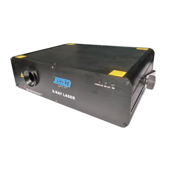
- Page 1 X-RAY LASER PROFESSIONAL LASER USER MANUAL Thank you for using our products. For the sake of safety and better operation of this product, please read this manual carefully before using and operating it.
-
Page 2: Power Cable
Before any first use, unpack the set and make sure there was no damage during transport. Check for missing any part supplied with the laser: 1 x X-RAY LASER 1 x POWER CABLE 1 x USER MANUAL GENERAL SAFETY INSTRUCTIONS This fixture must be earthed to in order to comply with the safety regulations and to avoid any electrical shock. -
Page 3: Installation Of The Unit
SAFETY INTRUCTIONS FOR LASERS According to EN/IEC 60825-1 regulations, this laser is classified under 4 class. Direct eye exposure can be dangerous DANGER: LASER RADIATION! UNIT UNDER 4 CLASS AVOID DIRECT EYE EXPOSURE. LASER RADAITION CAN CAUSE EYE DAMAGE AND/OR SKIN DAMAGE AVOID EXPOSTION TO LASER RADIATION ALL PROTECTIVE MEASURES MUST BE APPLIED FOR MAKING THE USE OF LASERS SAFE This product is a so-called show laser emitting radiation with a wavelength spectrum and producing lasers for shows. -
Page 4: Front Panel
Laser : Green 532 nm / 200 mW Red 650 nm / 600 mW Blue : 450 nm / 400 mW Mixed White : 1200 nW Working modes : DMX 512 (12 CH), Sound activation, Auto-beam, Auto-animation, Master/Slave, PC control Graphics &... -
Page 5: Function Settings
The system only accepts the DMX 512 signal to control the system mode: the laser pattern ON/OFF, the size, the position and the speed. DMX Control Parameters Chart Channel Function Value Description 0~49 Sound Active mode 50~99 Auto-Beam mode Mode 100~149 Auto-Animation mode 150~199... -
Page 6: Operation
DMX ADDRESS CALCULATION In DMX mode, the DIP switch from # 1 to # 9 should be set to record a DMX address. The address ranges from 1-511. Each dipswitch represents a binary value. Please refer to table below. Dipswitch VALUE Dipswitch VALUE... -
Page 7: Pc Control Operation
UNIVERSAL DMX MODE This mode allows you to use the DMX 512 console to operate your devices. Install the unit in a suitable and stable position. Use an XLR cable to connect devices together. Taken at the rear of the unit Assign a DMX address for each device using the DIP switch. - Page 8 Make sure the DMX mode is activated. Make sure the cables are of good quality and the connections are properly made. In DMX mode, the laser is not controlled by the DMX console, DMX signal indicator flashes. Make sure the console and the units have the same channel.
Need help?
Do you have a question about the X-RAY LASER and is the answer not in the manual?
Questions and answers