Table of Contents
Advertisement
Quick Links
FIRST, A WORD
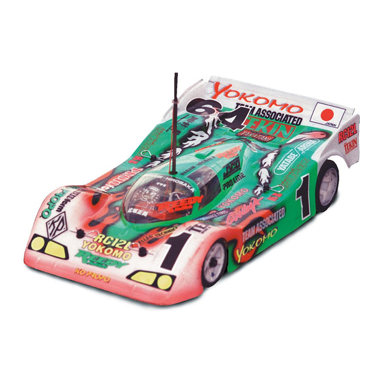
ABOUT THE NEW RC12LC
CONGRATULATIONS!! You have purchased the pro-
duction version of the car that Masami Hirosaka used to win the
1996/97 IFMAR 1/12 scale On Road World Championships.
This latest generation of the RC12L series car gives you more
improvements and features to enhance your performance.
Associated started in electric R/C with the original RC12E
which won numerous National Championships. This progressed
into the RC12I which won the very first 1982/83 1/12 scale
IFMAR World Championships held in Anaheim, California. It
then won the next 1984/85 IFMAR World Championships held
in Denmark. The RC12L, the next generation, dominated the
1986/87 Las Vegas, Nevada World Championships by taking
1st through 5th as well as Top Qualifier honors. This car was
again used to win the 1988/89 World Championships in Baarn,
Holland.
For the 1990/91 World Championships, in Singapore,
we redesigned the RC12L. The RC12LW as it was known, won
the 1990/91 Worlds and backed that win up by winning the
1992/93 World Championships in Grand Rapids, Michigan. We
then added our Dynamic Strut front suspension. This was given
the name RC12LS. It was also the car to own until we won the
1996/97 Worlds with your new RC12LC. The designation
RC12LC stands for Cliff Lett who designed the car.
The proven features that come with the RC12LC
include our Dynamic Strut front suspension (with our optional
caster change feature), Delta shock, Assoc. II rear axle assem-
bly, and dished one piece wheels. The new rear axle allows you
to change the right wheel without having to readjust the diff
each time. To go with these successful features, Cliff Lett and
the rest of our design team have relocated the dampener pivot
post for more consistent performance. You also have damp-
ener inserts to limit roll movement for quicker directional
changes. We added a front suspension cross brace and used
a new front suspension material. This makes the front suspen-
sion more rigid and more precise. The batteries were moved
closer to the centerline, and a fiberglass roll over antenna was
added to the new light weight antenna/shock mount. A new rear
chassis brace and symetrical T-bar were designed and a
graphite T-bar brace was added. It also comes with a new
precision lightweight left rear bulkhead for accurate bearing
alignment. The redesigned upper and lower pod plates along
with the left bulkhead make it easier to install, remove and
solder in the motor. What you end up with is a car that is easier
and faster to get dialed in to the track conditions. The 1996/97
IFMAR Worlds was the first race for the new 12LC. How did it
fare? In the A-main the 12LC finished in the top five positions
and took seven out of ten places. Your new car will show you
why Associated has won all but one of the 1/12 IFMAR World
Championships ever held!!
PLEASE READ THIS BEFORE
YOU BEGIN
We feel that our instruction manuals are the best in the
hobby. This is due to the number and quality of photos plus the
written information that explains each assembly. While it is
possible to assemble your kit only from the photos, we do not
recommend this. There is important facts or tips in the written
instructions that will help you to assemble your car for its best
performance and to prevent any delays due to assembly errors.
On road cars, while easier to assemble are more sensitive to
improper adjustments. So if you want to make your car the best
assembled car possible you will follow both the photos and
written instructions.
STEP 1
Open each parts bag when the instructions
indicate, not before. This is to help prevent parts from one bag
getting mixed up with parts from another bag. This kind of
mistake will cost you time and frustration while assembling your
car.
STEP 2
Check each parts bag for supplementary
instructions. Associated is always working on new designs
and materials to improve our products. This means that we will
occasionally make updates or changes to our kits. These
changes cannot be made immediately to the manuals, so we
use supplementary instructions to note changes. 1) Inspect
each bag upon opening it for the first time. Look for any pieces
of paper than have part and drawings showing what is being
changed. 2) When you do find one, locate the section of the
manual and parts list where these changes apply. 3) Note the
parts changes on the parts list then attach the supplement to
the appropriate assembly step in the manual. This will help
prevent delays in looking for the incorrect parts. It will also
reduce the chance of losing time taking something apart that
was assembled incorrectly due to use of the wrong parts.
STEP 3
Keep your parts separate. While building your car
it will be necessary to have more than one parts bag open at a
time. In order to prevent confusion we recommend using large
paper plates (especially picnic plates with partitions) to keep
parts from each bag spread out so that you can find them easily.
Mark each plate with the bag number or description before you
place the parts in them. When you have used all the parts from
one bag. You can then re-label the plate so that it can be used
for another bag.
STEP 4
Additional items needed to operate your car:
2 channel R/C, surface frequency, radio system (only one
servo is required). Because of limited space a small size
servo is recommended.
Battery pack (6-cell) needs to be assembled into a saddle
pack layout.
Battery charger, (we recommend the use of a peak
detection charger).
Electronic Speed Control (also referred to as an ESC).
R/C electric motor (will accept both stock and modified
motors).
Pinion Gear (48 pitch); size to be determined by type and
wind of motor you will be using.
4
Advertisement
Table of Contents

Subscribe to Our Youtube Channel
Related Manuals for Associated Electrics RC12LC


Summary of Contents for Associated Electrics RC12LC
- Page 1 1996/97 Worlds with your new RC12LC. The designation use supplementary instructions to note changes. 1) Inspect RC12LC stands for Cliff Lett who designed the car. each bag upon opening it for the first time. Look for any pieces The proven features that come with the RC12LC...
- Page 2 Figs. 1 & 2 We now want to take out the #4504 .084” RC12LC Graphite chassis. Look at both sides of the chassis. WARNING! We DO NOT recommend the use of a power The bottom will be the side with the countersunk holes. Before screwdriver to install screws into the nylon or composite parts.
- Page 3 dispose of the graphite filings or dust. Fig. 4 Before we start the assembly we need to locate the tools that come in your kit. Inside the Master kit bag you will find the #6950 tool bag. In this bag you will find three Allen wrenches.
- Page 4 #8407 upper arm mounts. Place the upper arm mount against impact the tool until it snaps into place. Note: always install the lower arm so the domes interlock. Make sure that the slant the pivot balls from the bottom of the lower front arm. We is facing down and to the front as shown in the photo.
- Page 5 Figs. 14 & 15 Remove the two remaining #8417 plastic pivot balls. Place one of the balls on the work bench shoulder side down. Place the square edge side of the upper arm eyelet over the pivot ball. Again use your thumb to snap the eyelet onto the pivot ball.
- Page 6 Also in bag #1 you will find the #4448 aluminum ball ends and the #4449 4-40 small aluminum locknuts. Remove two of each for this step. You will also need to remove the two #3213 front axles and two #6299 1/8” E-clips. The E-clips are held together by white tape.
- Page 7 T-BAR ASSEMBLY Fig. 21 Now we can open bag #2. Start by taking out the two #4335 plastic pivot sockets. There are two halves to each socket. Take one upper and lower portion of the pivot socket. This will become the front pivot socket. Look at the photo, you will see how much you must trim from each side of the two halves.
- Page 8 Fig. 25 Figs. 26 & 27 Still working with bag #2 remove the #4524 graphite T-bar brace, one #4519 4-40 x 9/16” FHSScrew, one #6915 4-40 x 5/8” FHSScrew, one #4449 4-40 small aluminum locknut, and the #4515 aluminum dampener center post.
-
Page 9: Rear End Assembly
Fig. 29 Fig. 32 Fig. 30 Fig. 33 REAR END ASSEMBLY Figs. 34 & 35 Open bag #4 and remove the #4532 Fig. 31 graphite lower pod plate, #4536 molded left side rear bulkhead, and three #6292 4-40 x 3/8” FHSScrews. Line the left rear bulkhead up with the three mounting holes in the lower pod Figs. - Page 10 Fig. 35 Fig. 37 Figs. 36 & 37 In the same bag you will find three #4526 plastic T-bar spacers and three #6292 4-40 x 3/8” Fig. 38 Now remove the #4530 graphite upper damp- FHSScrews, and three #4449 4-40 small aluminum locknuts. ener plate, one #4448 aluminum ball end, and one #4449 4-40 For the standard assembly we will only need two of each.
- Page 11 Fig. 39 Fig. 41 Fig. 42 Fig. 40 Figs. 41, 42 & 43 Now go back and get the remainder of bag #3 we set aside earlier. Take out one #4340 plastic dampener washer, one #8330 black O-ring, one #4517 dampener spring, one #6920 4-40 x 3/16”...
-
Page 12: Rear Axle Assembly
Fig. 44 Fig. 47 Fig. 45 REAR AXLE ASSEMBLY Fig. 48 Open bag #5 and remove the #4460 75 tooth 48 pitch spur gear and the bag containing the six #3432 1/8” diff balls. Now go to the master bag and remove the tube of #6636 Figs. - Page 13 To make the assembly easier, stand the axle on end so that the threaded end is facing up (we have laid the parts down to make the photo easier to shoot). Now take one of the #6579 drive rings, put a thin coat of diff lube on it and slip it over the end of the axle.
-
Page 14: Shock Assembly
Fig. 54 Fig. 56 Fig. 55 Fig. 57 SHOCK ASSEMBLY Figs. 58, 59 & 60 Now we can begin assembly of the Delta shock. Note: Associated does not have individual Figs. 56 & 57 replacement parts for the Delta shock, unless you see an Open bag #6, the shock bag, and Associated part number indicated in the photos and written remove the #4511 molded front shock/antenna mount, one... - Page 15 Fig. 58 Fig. 61 Fig. 59 Fig. 60 Fig. 62 Figs. 61, 62 & 63 From the master kit bag remove the bottle of #5415 20 weight shock oil. Now hold the shock body at a slight angle. Slowly add shock oil to the body. Let the oil run down the inside wall of the shock body to prevent air bubbles.
-
Page 16: Body Mount Assembly
Fig. 64 Fig. 67 Fig. 65 Fig. 66 Now attach the shock to the aluminum ball ends that are located on the shock/antenna mount and the rear Fig. 68 Now remove two #3320 front body mounts, two dampener plate. Make sure that the spring adjusting nut side of #3324 8-32 x ½”... - Page 17 National titles were also won with Reedy motors. If you are not sure which motor to get check with your local dealer or you are welcome to contact Associated at 714-850-9342 and we will do our best to assist you. We will start by installing the capacitors onto the motor.
- Page 18 Fig. 73 Fig. 74 STEERING SERVO & TIE-ROD ASSEMBLY Fig. 74 Now we need to set the gear mesh. This is accomplished by moving the motor forward or back. This Most radio systems come with standard medium size moves the pinion gear closer to or further away from the spur servos.
- Page 19 pivot point as possible. Use your #34 drill bit, or your 3/32” if you cannot find a #34 bit. After you have drilled out the holes install the two #4448 ball ends into the servo saver and thread the two #4449 locknuts onto the ends of the threads.
- Page 20 Also the right and left turnbuckles will be facing ins opposite directions as shown in fig. 81. Your new RC12LC is setup to run four or six cell saddle Snap the assembled turnbuckles onto the steering type battery packs. Some companies offer these in pre-as- block ball ends and the servo saver ball ends.
- Page 21 In order to connect the cells together you will need to reinforced strapping tape. The decision to use ½” ¾” or 1” tape use battery braid or battery bars. Normally battery braid is will be a personal choice. We do recommend that there be at cheaper and a little easier to solder, but the battery bars help to least two layers of tape on the bottom and where it comes up stiffen the battery pack when it is being handled.
-
Page 22: Electronic Speed Control Installation
RADIO RECEIVER INSTALLA- TION We are now ready to begin the installation of the radio receiver. If you have not already chosen your radio system, Associated recommends staying with a top name brand radio system. Names like Airtronics, Futaba, JRpropo, or KOpropo are the most recognized brands available. - Page 23 this location. Now use a piece of red wire, that was cut off the speed control when the motor positive lead was measured, to go between the red wire and the positive terminal of the battery pack. Fig. 95 shows all the battery and motor wires connected. Fig.
- Page 24 #6932 wheel screws do not go through the left wheel hub and touch the bulkhead. Go ahead and remove the two #3672 front wheels and tires. Go back to back #1 and remove two #4187 nylon front axle washer, and two #6299 1/8” E-clips. Any thing you have remaining in bag #1 will be spare parts (as long as you know you have assembled the car correctly).
-
Page 25: Final Adjustments
FINAL ADJUSTMENTS BATTERY CHARGING. Charge your transmitter bat- teries if they are Ni-Cads. This will normally require an over- night charge. Next charge the battery pack for your car. Do this according to the battery and/or battery charger instructions. Make sure all the speed control connections are according to the speed control manufacturers specifications. -
Page 26: Body Painting
You can then flex the body at the score line and peel off the part you want to remove. Be very You will find your RC12LC car will give you many hours careful around any sharp corners to prevent the body from of trouble-free operation. - Page 27 vent your losing unnecessary time in being able to enjoy your and so on. You can also have a very sensitive receiver. If your new car. radio problems persist, one of the following tips may help: MOTOR MAINTENANCE. After every 2 to 3 runs, re- Make sure your motor noise capacitors are properly move the brushes from the holders and inspect the tips for wear installed.
-
Page 28: Tuning Tips
Excessive negative camber will decrease traction but Your RC12LC has adjustable caster in increments of 2°. increase stability. Positive camber will also decrease traction With the 0° upper arm mounts you can have settings of 0°, 2°, and decrease stability. - Page 29 (soft) front-to-rear or decrease steering. In general a softer spring (smaller wire with very little effect on the side to side stiffness. Your RC12LC diameter) will add steering and a harder spring (larger wire di- will have more rear traction and will accelerate through bumps ameter) will decrease steering.
-
Page 30: Motor Gearing
the car smoother in the bumpy sections. Tire Tire Factor MOTOR GEARING Dia. Dia. ( 2.1" ÷ ÷ ÷ ÷ ÷ 1.9" ) = 1.105 You can get the most from your motor with the correct gearing. Old Pinion Factor Results New Pinion STOCK. - Page 31 One of the problems with Ni-Cds is their inherent charged at a high rate, and can release caustic chemicals if the voltage stability; the voltage of a fully charged cell is not much overcharge is severe. different from one that’s just about dead. For that reason Do not stall the motor under power.
Need help?
Do you have a question about the RC12LC and is the answer not in the manual?
Questions and answers