Table of Contents
Advertisement
Quick Links
SERVICE MANUAL
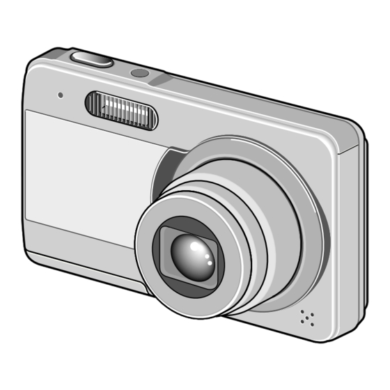
Digital Camera
Contents
1. OUTLINE OF CIRCUIT DESCRIPTION ............................... 3
2. DISASSEMBLY ................................................................... 12
3. ELECTRICAL ADJUSTMENT ............................................. 16
4. USB STORAGE INFORMATION REGISTRATION ............ 22
5. TROUBLESHOOTING GUIDE ............................................ 23
6. PARTS LIST ........................................................................ 24
CIRCUIT DIAGRAMS & PRINTED WIRING BOARDS ........... C1
RoHS
•This product does not contain any hazardous substances prohibited by the RoHS
Directive.
WARNING
•You are requested to use RoHS compliant parts for maintenance or repair.
•You are requested to use lead-free solder.
(This product has been manufactured using lead-free solder. Be sure to follow the
warning given on page 2 when carrying out repair work.)
CAUTION : Danger of explosion if battery is incorrectly replaced.
Replace only with the same or equivalent type recommended by the
manufacturer.
Discard used batteries according to the manufacturer's instructions.
NOTE : 1. Parts order must contain model number, part number, and description.
2. Substitute parts may be supplied as the service parts.
3. N. S. P. : Not available as service parts.
Design and specification are subject to change without notice.
SG216/U, EX, GX, U2, EX2, GX2 (R)
FILE NO.
VPC-E10
(Product Code : 168 143 01)
(U.S.A.) (Canada)
VPC-E10EX
(Product Code : 168 143 02)
(Europe) (U.K.) (South America)
(China) (Australia) (Hong Kong)
(Russia) (Middle East) (Africa)
(General) (Korea) (Taiwan)
VPC-E10GX
(Product Code : 168 143 03)
(South America) (China)
(Australia) (Hong Kong)
(General) (Korea) (Taiwan)
VPC-E10BK
(Product Code : 168 143 04)
(U.S.A.) (Canada)
VPC-E10EXBK
(Product Code : 168 143 05)
(Europe) (U.K.) (South America)
(China) (Australia) (Hong Kong)
(Russia) (Middle East) (Africa)
(General) (Korea) (Taiwan)
VPC-E10GXBK
(Product Code : 168 143 06)
(South America) (China)
(Australia) (Hong Kong)
(General) (Korea) (Taiwan)
REFERENCE No. SM5310741
Advertisement
Chapters
Table of Contents

Related Manuals for Sanyo VPC-E10


Summary of Contents for Sanyo VPC-E10
-
Page 1: Table Of Contents
FILE NO. SERVICE MANUAL VPC-E10 Digital Camera (Product Code : 168 143 01) (U.S.A.) (Canada) VPC-E10EX (Product Code : 168 143 02) (Europe) (U.K.) (South America) (China) (Australia) (Hong Kong) (Russia) (Middle East) (Africa) (General) (Korea) (Taiwan) VPC-E10GX (Product Code : 168 143 03) - Page 2 PRODUCT SAFETY NOTICE The components designated by a symbol ( ! ) in this schematic diagram designates components whose value are of special significance to product safety. Should any component designated by a symbol need to be replaced, use only the part designated in the Parts List.
-
Page 3: Outline Of Circuit Description
1. OUTLINE OF CIRCUIT DESCRIPTION 1-1. CCD CIRCUIT DESCRIPTION 1. IC Configuration The CCD peripheral circuit block basically consists of the fol- lowing ICs. IC914 (ICX665SQC) CCD imager IC905 (ADDI7000BCPZRL) CDS, AGC, A/D converter, H driver IC901 (LR366877) V driver 2. - Page 4 3. IC905 (H Driver) and IC901 (V Driver) 4. IC905 (CDS, AGC Circuit and A/D Converter) An H driver and V driver are necessary in order to generate The video signal which is output from the CCD is input to pins the clocks (vertical transfer clock, horizontal transfer clock and (25) of IC905.
- Page 5 1-2. CP1 CIRCUIT DESCRIPTION 1. Circuit Description 2. Outline of Operation 1-1. Signal processor When the shutter opens, the serial signals (“take a picture” 1. γ correction circuit commands) from the 8-bit microprocessor are input and op- This circuit performs (gamma) correction in order to maintain eration starts.
- Page 6 4. Lens drive block 4-1. Zoom drive The parallel signals (ZIN1 and ZIN2) which are output from the ASIC (IC101) are used to drive (ZOUT1 and ZOUT2) by the motor driver IC (IC951), and then used to drive the zoom DC motor.
- Page 7 1-3. PWA POWER CIRCUIT DESCRIPTION 1. Outline 3. (CH1) Motor System 4.2 V Output This is the main power circuit, and is comprised of the follow- 4.2 V is output. Feedback for the BOOST 4.2 V output is pro- ing blocks. vided to (Pin (C5) of IC501) so that PWM control can be car- Switching power controller (IC501) ried out.
- Page 8 1-4. ST1 STROBE CIRCUIT DESCRIPTION 1. Charging Circuit 2. Light Emission Circuit When UNREG power is supplied to the charge circuit and the When FLCLT signal is input from the ASIC, the stroboscope CHG signal from microprocessor becomes High (3.3 V), the emits light.
- Page 9 1-5. SYA CIRCUIT DESCRIPTION 1. Configuration and Functions For the overall configuration of the SYA block, refer to the block diagram. The configuration of the SYA block centers around a 8- bit microprocessor (IC301). The 8-bit microprocessor handles the following functions. 1.
- Page 10 SCAN OUT0 Keymatrix output BOOT input or COMREQ output ZBOOT_COMREQ CHG_DONE Strobo condensor charge done (L= done) Card detection (L= card detection) CARD AV JACK AV jack detection (L= detection) BAT_OFF Battery OFF detection signal input SREQ Serial communication request signal KEY_POWER Power key detection (using built-in pull-up) KEY_1st...
- Page 11 3. Key Operaiton For details of the key operation, refer to the instruction manual. SCAN SCAN SCENE PLAY MENU LEFT RIGHT DOWN TELE WIDE PW_TEST TEST Table 5-2. Key Operation 4. Power Supply Control The 8-bit microprocessor controls the power supply for the overall system. The following is a description of how the power supply is turned on and off.
-
Page 12: Disassembly
2. DISASSEMBLY 2-1. REMOVAL OF CABI BACK, LCD AND CABI FRONT 1. Two screws 1.7 x 4 12. Screw 1.4 x 5 2. Screw 1.4 x 3 13. Three screws 1.4 x 3.5 3. Screw 1.4 x 4 14. FPC 4. - Page 13 2-2. REMOVAL OF CP1 BOARD AND LENS 1. Remove the solder. (speaker) 8. Holder strap 2. Remove the solder. (microphone) 9. Two screws 1.4 x 3 3. Speaker, 8 10. CP1 board 4. Remove the solder. 11. Three screws 1.6 x 5 5.
- Page 14 2-3. REMOVAL OF ST1 BOARD 1. Microphone 2. Two screws 1.4 x 3 3. ST1 board 4. Cover triger 5. Remove the solder. 6. Assy, lamp – 14 –...
- Page 15 2-4. BOARD LOCATION ST1 board CP1 board – 15 –...
-
Page 16: Electrical Adjustment
Download the calibration software and the firmware IBM R -compatible PC with pentium processor from the following URL. USB port http://www.digital-sanyo.com/overseas/service/ 40 MB RAM Place the DscCalDi.exe file, camapi32.dll file and Hard disk drive with at least 15 MB available QrCodeInfo.dll file together into a folder of your... - Page 17 3-6. The adjustment item which in necessary in part exchange CCD Black CCD White Lens Lens Point And Point Factory Adjust- Adjust- White Point Language storage Reset Defect Adjust- Cord Defect Detect Setting ment ment information Setting Detect Setting ment Adjustment registration (60 cm)
- Page 18 AF_WIDE: ZW Adjustment method: ZW: adjustment value of focus at zoom position wide 1. Set the camera so that it becomes center of the siemens (–88<=ZW<=50) star chart in the collimator. (zoom wide and tele) AF_MID1: ZM1 (Set a distance of 0.5-1.0 cm between camera lens and ZM1: adjustment value of focus at zoom position middle1 collimator lens when zoom tele edge.
- Page 19 AF_I_MID7: ZIM7 Dsc Calibration ZIM7: infinity adjustment value of focus at zoom position middle7 (–197<=ZIM7<=112) AF_I_TELE: ZIT Copy ZIT: infinity adjustment value of focus at zoom position AWB Results: tele (–196<=ZIT<=89) AGC=173,342,508,677,845 3. AWB Adjustment 687,855 6F_AGC=0,0,0,0,0 MONIT_X1=173,173,173,173 WB=282,514,800 CHECK=128,128,145 MS=3055,3239 Fno_FOR_ISO=56 SS_FOR_ISO=2450...
- Page 20 5. CCD Black Point And White Point Defect Detect 3-8. Factory Code Setting Adjustment In Lighted 1. Check the "Factory Code" display within the Setting group. 2. For U.S.A., Canada and NTSC general area If "FC_SANYO_U" does not appear, click on the " "...
- Page 21 3-11. Reset Setting 3-13. Firmware uploading procedure Carry out reset settings after replacing CP1 board. 1. Uploading the firmware should be carried out if the version 1. Turn on the camera. number (COMPL PWB XX-X) on the replacement circuit 2. Press the MENU button. board is lower than the version of the distributed firmware.
-
Page 22: Usb Storage Information Registration
16.) 2. Double-click on the DscCalDi.exe. 3. Click on the Get button in the USB storage window and check the USB storage data. VID: SANYO PID: E10 Serial: Rev. : 1.00 4. -
Page 23: Troubleshooting Guide
5. TROUBLESHOOTING GUIDE POWER LOSS INOPERTIVE PW SW ON NORMAL SET PW SW ON (ON/OFF) CN101-5 CHECK ST1 LOW DETECTION IC302-7 CHECK F5001 MORE THAN 4.1 V CL190 CHECK IC302 (VDD) HIGH IC302-52 CHECK IC302, (RESET) R3006, CB302 HIGH IC302-4 CHECK IC302, (BAT OFF) R3007, C3006... -
Page 24: Parts List
636 112 5949 CARTON INNER-SG216/EX, 636 076 5344 STRAP-SX713/J VPC-E10EX,VPC-E10GX 645 083 3816 CABLE,DSC USB 7001 636 112 5932 CARTON INNER-SG216/U, VPC-E10 645 086 2687 CABLE,DSC USB 7001 636 116 1381 CARTON INNER-SG216/EX2, 645 083 3823 CABLE,DSC A/V VPC-E10EXBK,VPC-E10GXBK 645 086 2694... - Page 25 Table of accessories Table 6-1. Accessories...
- Page 26 636 115 9180 ASSY,CABI BACK-SG216/U, VPC-E10BK,VPC-E10EXBK,VPC-E10GXBK VPC-E10BK,VPC-E10EXBK,VPC-E10GXBK 636 111 9375 STAND-SG2RU, 312 064 3508 SPECIAL SCREW-1.7X4.0, VPC-E10,VPC-E10EX,VPC-E10GX VPC-E10, VPC-E10EX,VPC-E10GX 636 115 7513 STAND-SG216/U, 411 199 1004 SCR S-TPG TIN 1.7X4, VPC-E10BK,VPC-E10EXBK,VPC-E10GXBK VPC-E10BK,VPC-E10EXBK,VPC-E10GXBK 636 111 9719 DEC RIGHT-SG216/U 411 191 3303 SCR PAN PCS 1.4X5...
- Page 27 CABINET AND CHASSIS PARTS 1 CABINET & CHASSIS PARTS 1 SG216/J Parts List 1...
-
Page 28: Cabinet And Chassis Parts 2
CABINET AND CHASSIS PARTS 2 LOCATION PARTS NO. DESCRIPTION LOCATION PARTS NO. DESCRIPTION 636 113 8031 ASSY,HL BOTTOM-SG216/U, 636 111 8286 SPACER LPF SG2RU VPC-E10,VPC-E10EX,VPC-E10GX 645 095 8717 OPTICAL FILTER 636 115 9289 ASSY,HL BOTTOM-SG216/U, 636 111 8293 SPACER SG2RU VPC-E10BK,VPC-E10EXBK,VPC-E10GXBK 636 115 6783... - Page 29 CABINET & CHASSIS PARTS 2 CABINET AND CHASSIS PARTS 2 SG216/J Parts List 2...
-
Page 30: Electrical Parts
ELECTRICAL PARTS Note: 1. Materials of Capacitors and Resistors are abbreviated as follows ; Resistors Capacitors MT-FILM Metallized Film Resistor MT-POLYEST Metallized Polyester Capacitor MT-GLAZE Metallized Glaze Resistor MT-COMPO Metallized Composite Capacitor OXIDE-MT Oxide Metallized Film Resistor TA-SOLID Tantalum Solid Capacitor AL-SOLID Aluminum Solid Capacitor NP-ELECT... - Page 31 LOCATION PARTS NO. DESCRIPTION LOCATION PARTS NO. DESCRIPTION C1413 303 276 1000 CERAMIC 0.01U K 16V C9070 303 314 5304 CERAMIC 5P C 50V C1701 303 397 7608 CERAMIC 1U K 25V C9071 303 314 5304 CERAMIC 5P C 50V C1702 303 397 7608 CERAMIC...
- Page 32 LOCATION PARTS NO. DESCRIPTION LOCATION PARTS NO. DESCRIPTION R5081 401 352 6908 MT-GLAZE 680K CC 1/16W C5410 303 428 3302 CERAMIC 0.022U K 350V R5082 401 352 6809 MT-GLAZE 120K CC 1/16W C5411 303 428 3609 CERAMIC 0.01U K 350V R5083 301 224 9306 MT-GLAZE...
- Page 33 CIRCUIT DIAGRAMS & PRINTED WIRING BOARDS TABLE OF CONTENTS OVERALL WIRING & BLOCK DIAGRAMS Page OVERALL WIRING ............................C3 OVERALL CIRCUIT ............................C4 CCD CIRCUIT ..............................C5 LENS CIRCUIT ..............................C5 MAIN CIRCUIT ..............................C6 POWER CIRCUIT ............................C7 STROBE CIRCUIT ............................C7 SYSTEM CONTROL CUIRCUIT ........................
- Page 34 NOTES: 1. All resistance values in "OHMS" unless otherwise noted. (K=1,000 ; M=1,000,000) µ 2. All capacitance values in " F" unless otherwise noted. µ p=pico farad ; ,u or U=micro farad µ 3. All inductance values in " H" unless otherwise noted. µ...
-
Page 35: Overall Wiring & Block Diagrams
OVERALL WIRING & BLOCK DIAGRAMS OVERALL WIRING LCD BACKLIGHT Zoom PI E Zoom PI K Zoom PI AC Zoom Motor (-) Zoom Motor (-) Zoom Motor (+) Zoom Motor (+) Aperture (-) Aperture (-) Aperture (+) Aperture (+) Shutter (+) Shutter (+) Shutter (-) Shutter (-) -
Page 36: Overall Circuit
OVERALL CIRCUIT CP1 BOARD PROGRAM FLASH SDRAM 64Mbyte/64Mbyte TO ASIC (ENCODER) SDRAM BUFA EXTERNAL CDS, AGC, A/D C CONTROLLER H. DRIVER CA1 BOARD JPEG CONTROLLER BUFD V. DRIVER 10M CCD SG/TG USBD(+), D(-) TO USB AEAF AUDIO SD CARD DMA(LENS) BUF-BC SYSTEM LENS... -
Page 37: Ccd Circuit
CCD CIRCUIT LENS CIRCUIT VDD3 CN951 +13V(A) -7.5V(A) LENS_BLOCK LENS O_LPF Q9102 LENS_TEMP CCDINP LENS_TEMP THERMISTOR VOUT AFESD2P AFESD2P (IC101 Y14pin) IC905 AFDSD2N IC914 AFDSD2N øLH1 ADDI7000BCPZRL ICX665SQC AFECKP AFECKP VDD3 CDS, AGC, A/D C 10M CCD AFECKN AFECKN BOOST4.2V VDD3 H. -
Page 38: Main Circuit
MAIN CIRCUIT CA1 BOARD LENS BLOCK LENS BLOCK IC914 ICX665SQC IC905 CN901 LENS IC901 IC951 10M CCD ADDI7000BCPZRL CN951 LR366877 LV8056LP-TLM CDS, AGC, A/D C V. DRIVER LENS DRIVER H. DRIVER SPEAKER AUDIO BLOCK AUDIO BLOCK LCD BLOCK LCD BLOCK LMCLK ADCDAT LCDCK... -
Page 39: Power Circuit
POWER CIRCUIT STROBE CIRCUIT CHARGING CIRCUIT IC501 PWM/PFM BD9631GU C5401 T5401 D5402 SWITCHING XSHDN34 PREV1 POWER FILTER CONTROL OSCILLATION RECTIFIER C5412 XSHDN2 TRANSFORMER CIRCUIT BLOCK PREV6 L5301, D5301, Q5301 BOOST4.2V STEP UP CIRCUIT CN541 XSHDN78 OUT1 PAON IC502 TO DMA UNREGST +3.5V(A) XSHDN6... -
Page 40: Circuit Diagrams
CIRCUIT DIAGRAMS SYSTEM CONTROL CIRCUIT CIRCUIT WAVEFORMS BOOST4.2V TEST POINT TEST POINT TO DMA WAVEFORM WAVEFORM LOCATION LOCATION AL3.2V BACKUP3.2V IC301 IC101 CN171 UNREGSY ZCHGDONE 8bit MICRO PROCESSOR TO DMA PIN AC15 PIN 4 Q3001 LC87F2924BUFL64TBM C22M IC302 IC303 BATTERY BAT_T RESET VDD2... -
Page 41: Cp1 Board (Dma) Main
CP1 BOARD (DMA) MAIN DMA (LCD) DMA (LENS) DMA (MAIN) A_VDD3 D1-14300/SG216-U VOLTAGE: VIEW MODE, LCD ON VDD3 TO LCD CN171 1608 C1701 1AV4J11FL410G ZPI_E R9505 1;B 25 1608 Zoom PI E C1702 390;1/16J ZPISW Zoom PI K C21M Zoom PI AC A_VDD1.2 D1701 C21P... - Page 42 CP1 BOARD (DMA) MAIN [UPPER-LEFT] DMA (MAIN) A_VDD3 D1-14300/SG216-U VOLTAGE: VIEW MODE, LCD ON A_VDD1.2 1608 R1002 0;1/16Z VDD1.2 VDD3 R1001 0;1/16Z 1608 A_VDD3 DSCKN AB14 VDD_IO DSCKN ZCAS AB8 VDD_IO ZCAS ZDSCS B20 VDD_IO ZDSCS ZDSWE AB20 VDD_IO ZDSWE ZRAS B14 VDD_IO_gA ZRAS...
- Page 43 CP1 BOARD (DMA) MAIN [UPPER-RIGHT] DMA (LCD) DMA (LENS) VDD3 TO LCD CN171 1608 C1701 1AV4J11FL410G ZPI_E R9505 1;B 25 1608 Zoom PI E C1702 390;1/16J ZPISW Zoom PI K C21M Zoom PI AC D1701 C21P HSC226-E C1703 Zoom Motor (-) 1608 C22M ZOUT2...
- Page 44 CP1 BOARD (DMA) MAIN [LOWER-LEFT] TO PWA M16 VSS_CORE N16 VSS_CORE AVSS33A1_ADC AA10 P16 VSS_CORE AVDD33A1_ADC AB10 A21 VSS_CORE COMPAO AC11 AC21 VSS_CORE VREFAO AC10 A22 VSS_CORE AOUT B22 VSS_CORE AVDD33A_ADAC AB22 VSS_CORE AVSS33A_ADAC AC22 VSS_CORE VREFV A23 VSS_CORE IREFV B23 VSS_CORE COMPV C23 VSS_CORE...
- Page 45 CP1 BOARD (DMA) MAIN [LOWER-RIGHT] AVSS33A1_ADC AA10 AVDD33A1_ADC AB10 COMPAO AC11 VREFAO AC10 AOUT AVDD33A_ADAC AVSS33A_ADAC VREFV IREFV VDD3 COMPV AVDD33A_VDAC AVSS33A_VDAC YOUT YOUT AVDD33D_VDAC CN141 1AV4J11B8300G R1401 DATA3 100;1/16J AA3 AB3 AA4 AB4 AC4 Y5 AB5 AC5 Y6 AC6 Y7 AC7 AC8 AA6 SDCMD COMMAND...
-
Page 46: Cp1 Board (Pwa) Power
CP1 BOARD (PWA) POWER CL502 BAT_T BAT_T BAT_T TO SYA P1-14300/SG216-U VOLTAGE: VIEW MODE, LCD ON (USE BATTERY) 1608 F5002 CL503 2A32V UNREG UNREGST BATT+ UNREGST TO DMA UNREGSY TO SYA CL504 BOOST4.2V BATT- BOOST4.2V TO BATTERY 1608 F5001 +3.5V(A) 2A32V PAON4 R5017... -
Page 47: Cp1 Board (Sya) System Control
CP1 BOARD (SYA) SYSTEM CONTROL Y1-14300/SG216-U VOLTAGE: VIEW MODE, LCD ON BOOST4.2V BOOST4.2V ZJACKIN ZBOOT_COMREQ ZCARD ZCHGDONE TO DMA PLLEN BLON TO PWA USBCNT AL3.2V AL3.2V TO DMA BACKUPCTL BACKUP3.2V C3012 SCAN OUT 1 P05/CK0 SCAN IN 1 SCAN OUT 2 VSS3 MRST SCAN IN 3... -
Page 48: Cp1 Board (Caa) Ccd Afe & Driver
CP1 BOARD (CAA) CCD AFE & DRIVER C2-14300/SG216-U VOLTAGE: VIEW MODE, LCD ON IC901 R9001 0;1/16Z LR366877 -7.5V(A) -7.5V(A) R9002 QLR366877---J +13.0V(A) 0;1/16Z +3.5V(A) V. DRIVER R9003 VDD3 VDD3 0;1/16Z PAON3 Q9002 PAON3 UP0421500 R9040 390K;1/16J XV13 V10X V17X XSG8 XSG3 XSUB VH17AX... -
Page 49: Ca1 Board Ccd
CA1 BOARD CCD C1-14300/SG216-U CN911 VOLTAGE: VIEW MODE, LCD ON 1AV4J11JV400G R9101 -1.2 -5.1 Vø5C Vø1A SUBCONT 300;1/16J SUBCONT V6S1 -5.1 Vø6S1 VGND V6S1 V6S1 V6S2 -3.7 -5.1 Vø6S2 øLV V6S2 Q9102 V6S2 UP05C8P00 VST2 -0.1 -7.4 VøST2 øVOG VST2 VST2 VST1 -7.5... -
Page 50: St1 Board Strobe
ST1 BOARD STROBE FLASH REFLECTOR S1-14300/SG216-U VOLTAGE: STROBE AFTER CHARGE T5401 TTRN-0530H-001-T JW541 AWG30 UNREGST D5402 BROWN 2.0X1.25 FV02R80TP R5435 100;1/16J STROBE CHARGE IC541 BD4218NUV QBD4218NUV--P C5410 PGND RB541 0.022;350B 3216 1KX4 1/16W IGBT_OUT 1AV4L17B0450N C5431 IGBT_IN T5402 TS-F35A-3 FULL C5432 START 3216... -
Page 51: Printed Wiring Boards (P.w.b.)
PRINTED WIRING BOARDS (P.W.B.) CP1 P.W.B. (SIDE A) CP1 P.W.B. (SIDE B) -
Page 52: St1 P.w.b. (Side A & B)
ST1 P.W.B. (SIDE A) ST1 P.W.B. (SIDE B) -
Page 53: Ca1 P.w.b. (Side A & B)
CA1 P.W.B. (SIDE A) CA1 P.W.B. (SIDE B) - Page 55 SANYO Electric Co., Ltd. Osaka, Japan Printed in Japan Feb./’08...
Need help?
Do you have a question about the VPC-E10 and is the answer not in the manual?
Questions and answers