Table of Contents
Advertisement
Advertisement
Table of Contents

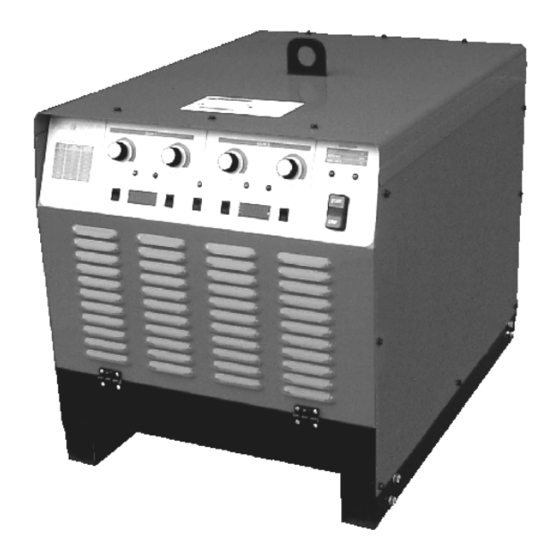
Summary of Contents for Pro-Weld ARC 1850
- Page 1 OPERATION/ MAINTENANCE MANUAL...
-
Page 3: Table Of Contents
WEL D ARC 1 8 5 0 TABLE OF CONTENTS PAGE INTRODUCTION............WARRANTY............... UNPACKING YOUR UNIT........SUGGESTED SAFETY PRECAUTIONS..…..1 PERSONAL SAFETY PRECAUTIONS……………. 1 POWER SUPPLY SAFETY PRECAUTIONS…….. 2 GENERAL DESCRIPTION......…... 2 ELECTRICAL INPUT REQUIREMENT..…..2 CONTROL PANEL DESCRIPTION.....…..4 WELD GUN SETUP.........….. - Page 4 WEL D ARC 1 8 5 0...
- Page 5 WEL D ARC 1 8 5 0...
- Page 6 WEL D ARC 1 8 5 0...
- Page 7 WEL D ARC 1 8 5 0...
-
Page 8: Introduction
WEL D ARC 1 8 5 0 Your unit has been completely assembled and inspected at 1.0 INTRODUCTION the factory. Upon receipt, the unit must be hooked up to the recommended incoming power before welding. Your new stud welding equipment has been carefully con- structed using the finest components and material available. -
Page 9: Power Supply Safety Precautions
WEL D ARC 1 8 5 0 9. Be sure to provide proper ventilation when welding in a con- A specially designed electronic gun control circuit has been fined area. incorporated in this system. If a fault condition occurs due to a 10. -
Page 10: Jumper Link Arrangement
WEL D ARC 1 8 5 0 230V 460V Figure 1 575V Jumper Link Arrangement Jumper Link connections CAUTION PRIMARY WIRE DELAY TYPE FUSE The stud labeled GND is connected to the unit chassis and is for grounding purposes only. Do not connect a wire SIZE- SIZE IN AMPS from the terminal labeled GND to one of the three-phase... -
Page 11: Control Panel Description
WEL D ARC 1 8 5 0 Figure 2 CONTROL PANEL FRONT (DUAL GUN SYSTEM) WELD/CURRENT ADJUSTMENT 7.0 CONTROL PANEL DESCRIPTION Select: SETUP, CURRENT and adjust the current control START/STOP PUSH BUTTON knob until the digital meter displays the desired current. Re- turn setup switch to WELD, before attempting to weld. -
Page 12: Weld Gun Setup
(see PRO WELD Accessories catalog for help in this 7. Place the gun, loaded with the stud and ferrule, squarely area). -
Page 13: Checking Gun Lift
WEL D ARC 1 8 5 0 8.2 Checking Gun Lift To measure lift, turn the stud welding unit on and set the timer to maximum time. (On certain units there may be a Lift Check switch available, and in these cases this switch can be used 1 AMP to check lift.) Trigger the gun in the air, or on a non-grounded or insulated surface, to observe the lift cycle. -
Page 14: Control Unit - Front
WEL D ARC 1 8 5 0 Figure 5 Control Unit (Front View) 9.0 PARTS LIST ITEM DESCRIPTION PART NUMBER Switch 104-0014 On/Off Operator 104-0016 N.O. Contact 104-0017 N.C. Contact 104-0018 Power Light (Green Neon) 102-0087 Knob 102-0060 20k Potentiometer 111-0012 Red LED 108-0028... -
Page 15: Control Unit - Rear
WEL D ARC 1 8 5 0 Figure 6 Control Unit Rear 9.0 PARTS LIST ITEM DESCRIPTION PART NUMBER Fuse 6 amp 600 volt 102-0007 Control Transformer 105-0015 Fan Blade 14” 102-0083 Fan Motor 102-0085 Start Contactor 113-0017 PAGE 8... -
Page 16: Control Unit -Side View
WEL D ARC 1 8 5 0 FRONT OF UNIT Figure 7 Control Unit Side View 9.0 PARTS LIST ITEM DESCRIPTION PART NUMBER Main Transformer 105-0023 Shunt 102-0107 PAGE 9... -
Page 17: Rectifier, Weld Bridge Assy
WEL D ARC 1 8 5 0 Figure 8 RECTIFIER, SCR ASSEMBLY SIDE AND TOP VIEW 9.0 PARTS LIST ITEM DESCRIPTION PART NUMBER Weld SCR Thermostat 102-0032 Weld SCR Clamp 102-0109 Weld SCR 108-0058 PAGE 10... -
Page 18: Printed Circuit Board Enclosure
WEL D ARC 1 8 5 0 Figure 9 Printed Circuit Board Enclosure Top and Side View Front of Unit 9.0 PARTS LIST ITEM DESCRIPTION PART NUMBER Choke Coil 105-0004 Time Control P.C.Board 600-0010 Current Control P.C.Board 600-0012 Monitor Control P.C.Board 600-0011 Time Control P.C.Board 600-0010... -
Page 19: Gun Timer Control Pcb
WEL D ARC 1 8 5 0 D120 V106 V104 C107 C108 + C105 D127 ZD105 R126 R153 C104 R141 R127 D124 V107 V103 D110 V111 R111 V105 R154 R137 VR101 R102 D101 R148 D140 C101 C114 C113 R107 D121 R133 Figure 10 GUN TIME CONTROL P.C. -
Page 20: Monitor Pcb
WEL D ARC 1 8 5 0 VR201 V201 V205 V202 C202 V207 V206 C208 V204 C206 V203 C209 R204 D210 Figure 11 MONITOR P.C. BOARD P/N 600-0011 PAGE 13... -
Page 21: Current Control Pcb
WEL D ARC 1 8 5 0 V304 R332 R345 D316 R331 R347 D318 R304 C306 R302 C305 Q301 D320 D328 C308 TR301 V302 V305 V303 D313 R341 R328 D321 C311 R327 D322 D324 C301 R333 D325 D323 R350 D326 D327 Figure 12 CURRENT CONTROL P.C. -
Page 22: Trouble Shooting
WEL D ARC 1 8 5 0 10.0 TROUBLE SHOOTING Whenever possible, have a qualified electrician do the maintenance and trouble shooting work. Turn the input power off us- ing the disconnect switch at the fuse box before working inside the machine. Trouble Possible Cause What To Do... - Page 24 MANUFACTURED BY WELD MADE IN THE U.S.A.


Need help?
Do you have a question about the ARC 1850 and is the answer not in the manual?
Questions and answers