Table of Contents
Advertisement
Advertisement
Table of Contents
Troubleshooting

Related Manuals for Pro-Weld CD-512


Summary of Contents for Pro-Weld CD-512
- Page 1 OPERATION/ MAINTENANCE MANUAL...
-
Page 3: Table Of Contents
CAUSES OF POOR OR ERRATIC WELDS 14.0 TROUBLE SHOOTING POOR WELDS 15.0 ROUTINE WELDER MAINTENANCE 16.0 ASSEMBLY –CD-512 CONTROLLER 16,17,18 16.1 PC Board Assembly Drawing 17.0 TROUBLE SHOOTING – ELECTRICAL 18.0 CHECK LIST CD-512 SYSTEM P.N. 100-0110 19.0 CHECK LIST CD-512 SYSTEM P.N. 100-0111... -
Page 4: List Of Figures
WEL D CD -5 1 2 LIST OF FIGURES CD CONTACT PROCESS STRAIGHT POLARITY HOOK-UP REVERSE POLARITY HOOK-UP FRONT PANEL LAYOUT STANDARD GUN SETUP COLLET PROTECTOR SETUP TEMPLATE ADAPTER GUN SETUP COLLET PROTECTOR/BLUNT LEG SETUP HEAVY DUTY CD GUN HOT WELD COLD WELD ARC BLOW WELD WITHOUT FOOTPIECE... - Page 5 WEL D CD -5 1 2...
- Page 6 WEL D CD -5 1 2...
- Page 7 WEL D CD -5 1 2...
- Page 8 WEL D CD -5 1 2...
-
Page 9: Introduction
WEL D CD -5 1 2 1.0 INTRODUCTION 3.0 UNPACKING YOUR UNIT Your new stud welding equipment is carefully Upon receipt of your unit, place it as close as constructed of the finest components and materials possible to the point of installation before unpacking available. -
Page 10: General Description
(SEE FIGURE 1). Verify that the gun is held perpendicular to the work. Pulling the trigger The CD-512 portable CD welder is a self con- discharges the capacitors through the stud which va- tained heavy duty capacitor discharge power supply porizes the tip. -
Page 11: Power Requirements
WEL D CD -5 1 2 This technique, when equipment is set up properly, Capacitance: is simple and easily mastered. The same power sup- 84,000 uF nominal Low Range ply is capable of welding many different sizes and 168,000 uF nominal High Range materials of fasteners. -
Page 12: Welding System Hook-Up
WEL D CD -5 1 2 9.0 WELDING SYSTEM HOOK-UP Straight Polarity (Standard Set-Up) (see Figure 2(shown with dual grounds)) A. Connect ground cable connector (1A) into camlok (1). The camlok should be connected into the receptacle marked GROUND. Twist until it locks. Attach “C” clamp (2) to the workpiece (5) (CLEANED AREA). -
Page 13: Reverse Polarity
WEL D CD -5 1 2 9.2 Reverse Polarity (Recommended for brass or galvanized) (see Figure 3) A. Connect ground cable connector (1A) into camlok (4). The camlok should be connected into the receptacle marked GUN. Twist until it locks. Attach “C” clamp (2) to the workpiece (5) (CLEANED AREA). -
Page 14: System Operation
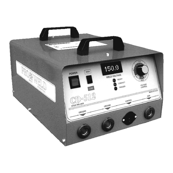
10.0 SYSTEM OPERATION (see Figure 4) The CD-512 is designed for simple, yet precise operation. It has an “ON-OFF” toggle switch/indicator light (1) a High/Low range selection switch (2),a variable voltage control dial (3) a ready indicator light (4), a contact light (5) and a trigger light (6) on the front panel. - Page 15 WEL D CD -5 1 2 Setting the Weld Voltage/Capacitance HIGH RANGE 60 – 100 VDC 1/4” Slowly turn the voltage control knob 100 – 140 VDC 5/16” clockwise to increase the weld voltage until the 140 – 170 VDC 3/8”...
-
Page 16: Gun Set-Up
WEL D CD -5 1 2 11.0 GUN SET-UP For CD welding, the stud normally should be 11.1 STANDARD (see Figure 5) engaged for all but 1/4” of its length, whenever pos- sible. Selecting the proper stop will accomplish this The standard gun set-up is used for welding the for you. -
Page 17: Installing Or Changing Collets Or Chucks
WEL D CD -5 1 2 The gun is now ready to weld. Select the 1. It does not require a pin stop. proper setting for the size stud to be welded. Voltage therefore, the same setup is applicable is determined by the weld base diameter. Be sure for a range of pin lengths. -
Page 18: Template Adapter
WEL D CD -5 1 2 11.4 TEMPLATE ADAPTER (see Figure 7) 11.5 COLLET PROTECTOR/BLUNT LEG (see Figure 8) The template adapter is used when precise location or positioning of the CD stud is required. The round faceplate, with blunt legs, can alter- It is used with the round faceplate and does not re- nately be used with the collet protector as shown in quire a footpiece or legs. -
Page 19: Heavy Duty Cd Gun
WEL D CD -5 1 2 Figure 10 Heavy Duty CD Gun PAGE 11... -
Page 20: Parts List Hd Cd Handgun
WEL D CD -5 1 2 11.6 PARTS LIST LIGHT DUTY CD HANDGUN Part No. 300-0100 ITEM PART NO. DESCRIPTION 033-384 GUN (CD) REAR CAP MOLDED 001-801 SPRING MAIN HEAVY BLACK 033-610 GUN (CD/DA) BEARING ASSEMBLY 033-799 GUN (CD) SHAFT TUBE 033-016 HEX HEAD CAP SCREW 033-382... -
Page 21: Weldable Material Combinations
WEL D CD -5 1 2 12.0 WELDABLE MATERIAL COMBINATIONS BASE MATERIAL STUD MATERIALS Mild Steel (1008-1018) Mild Steel 1008, 1018 Stainless Steel 304, 305 Brass 65-35, 70-30 Copper, Silicon/Bronze Galvanized Sheet (duct-”Q” Decking Mild Steel 1008-1018 Stainless Steel 304,305 Structural Steel (Must Be Clean) Mild Steel 1008,1018 Stainless Steel 304,305... -
Page 22: Causes Of Poor Or Erratic Welds
WEL D CD -5 1 2 13.0 CAUSE OF POOR OR ERRATIC 12. Incorrect spring. (REPLACE WITH PROPER WELDS SPRING) 1. Loose collet. Does not grip stud tightly. 13. Poor stud quality. (REPLACE) Not enough engagement of stud to col- let. -
Page 23: Routine Welder Maintenance
WEL D CD -5 1 2 15.0 ROUTINE WELDER MAINTENANCE Your CD-312 is designed for long service with minimum care. Ordinary common sense mainte- nance will keep it operating efficiently. 1. Treat the welding, ground, and control ca- bles with respect. Avoid sharp bends and kinks which Figure 13 Arc Blow may break the cables. -
Page 24: Assembly -Cd-512 Controller
WEL D CD -5 1 2 16.0 ASSEMBLY CD-512 CONTROLLER (see Figure 15,16, & 17) Figure 16 Parts List ITEM DESCRIPTION PART NUMBER SCR Mounting 124-0026 Main SCR 108-0001 Buss Bar 124-0043 Buss Bar 124-0038 Dropping Resistor 112-0042 Transformer 105-0010... - Page 25 WEL D CD -5 1 2 Figure 17 Parts List ITEM DESCRIPTION PART NUMBER PC Board 600-0007 Buss Bar 124-0042 Buss Bar 124-0041 Buss Bar 124-0039 Diode 108-0005 Capacitor (8) 106-0001 Diode 108-0027 PAGE 17...
- Page 26 WEL D CD -5 1 2 Figure 18 Parts List ITEM DESCRIPTION PART NUMBER Female Camlok (3) 107-0002 2-Pole Female Hubble 107-0031 LED Amber (Contact) 108-0030 Knob 102-0060 LED Panel Meter 103-0002 High-Low Range Switch 104-0014 Power Switch 104-0013 LED Green (Ready) 108-0029 LED Red (Trigger) 108-0028...
-
Page 27: Pc Board Assembly Drawing
WEL D CD -5 1 2 16.1 PC BOARD ASSEMBLY DRAWING FU2 and FU3 are 3AG 1 ampere fuses Figure 19 PC Board PAGE 19... -
Page 28: Trouble Shooting - Electrical
WEL D CD -5 1 2 17.0 TROUBLE SHOOTING – ELECTRICAL When troubleshooting the power unit/controller (welder), the following precautions must be observed: 1. Welder must be TURNED OFF! 2. Unplug power cable from welder and wait at least two minutes before checking components. 3. - Page 29 WEL D CD -5 1 2 PROBLEM POSSIBLE CAUSE CORRECTIVE ACTION 3. Welder turns on but A. Ground cable connections Check for continuity does not operate not complete. *B. Broken gun control cable Check continuity between or loose wire connection pins on control plug while in the plug.
-
Page 30: Check List Cd-512 System P.n. 100-0110
GROUND CABLE #2 X 15’ (2 REQUIRED) 125-0101 MANUAL, Operation and Maintenance CD-512 HEX WRENCH SET 19.0 CHECK LIST CD-512 SYSTEM PT. NO. 100-0111 STANDARD CD-512 WELDING SYSTEM COMPLETE WITH TAPER TIP GUN AND 25’ #2 GROUND CABLE ITEM DESCRIPTION PART #... - Page 32 MANUFACTURED BY WELD MADE IN THE U.S.A.
Need help?
Do you have a question about the CD-512 and is the answer not in the manual?
Questions and answers