Table of Contents
Advertisement
Advertisement
Table of Contents

Related Manuals for Pro-Weld ARC 656-575 VERSION


Summary of Contents for Pro-Weld ARC 656-575 VERSION
- Page 1 575 V ERSIO N OPERATION/ MAINTENANCE MANUAL...
-
Page 3: Table Of Contents
WEL D ARC 6 5 6 TABLE OF CONTENTS tion SAFETY PRECAUTIONS PAGE INTRODUCTION............WARRANTY............... UNPACKING YOUR UNIT........SUGGESTED SAFETY PRECAUTIONS....PERSONAL SAFETY PRECAUTIONS……………. POWER SUPPLY SAFETY PRECAUTIONS……… GENERAL DESCRIPTION........ELECTRICAL INPUT REQUIREMENT....CONTROL PANEL DESCRIPTION...... WELD GUN SETUP........... PLUNGE LENGTH............. CHECKING GUN LIFT.......... - Page 4 WEL D ARC 6 5 6...
- Page 5 WEL D ARC 6 5 6...
- Page 6 WEL D ARC 6 5 6...
- Page 7 WEL D ARC 6 5 6...
-
Page 8: Introduction
WEL D ARC 6 5 6 Your unit has been completely assembled and inspected at 1.0 INTRODUCTION the factory. Upon receipt, the unit must be hooked up to the recommended incoming power before welding. Your new stud welding equipment has been carefully con- structed using the finest components and material available. -
Page 9: Power Supply Safety Precautions
WEL D ARC 6 5 6 9. Be sure to provide proper ventilation when welding in a confined area. Primary Connection Voltage 10. Never look at the electric arc without wearing protective eye shields. 11. Always use the proper protective clothing, gloves, etc. 12. -
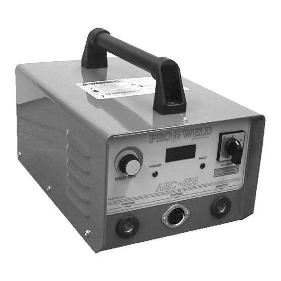
Page 10: Control Panel Description
WEL D ARC 6 5 6 GROUND FIGURE 2 FIGURE 3 CONTROL PANEL FRONT CAUTION The stud labeled GND is connected to the unit chassis and is for grounding purposes only. Do not connect a wire from the If there is a gun fault, by unplugging the gun control cable at terminal labeled GND to one of the three-phase line termi- the welder the LED will be “off”... -
Page 11: Checking Gun Lift
WEL D ARC 6 5 6 Plunge Length Locking Screws Ferrule Chuck Chuck Adapter Stud Ferrule Grip (2) Foot Screws Foot Leg Adj. Screw FIGURE 4 3. The “plunge length” is the amount of the stud exposed be- yond the ferrule during initial set-up. Set the plunge by loos- 9. -
Page 12: Setting Up The Power Source
WEL D ARC 6 5 6 When it does become necessary to adjust lift, you do so by removing the rear cap from the gun. This will expose the 9.2 Weld Test and Inspection rear coil yoke assembly, the set screw and the lift adjusting screw Testing of weld quality beyond visual inspection varies (Loosen the set screw to avoid damaging the threads of the lift adjusting screw). -
Page 13: Maintenance
WEL D ARC 6 5 6 A. Bend Test CAUTION Repeatedly bend the stud away from its axis until failure occurs. Read and follow the safety information at the beginning B. Torque Test - Threaded Studs of this section before proceeding. Twist the stud to point of failure. -
Page 14: Trouble Shooting
WEL D ARC 6 5 6 11.0 TROUBLE SHOOTING Whenever possible, have a qualified electrician do the maintenance and trouble shooting work. Turn the input power off us- ing the disconnect switch at the fuse box before working inside the machine. Trouble Possible Cause What To Do... -
Page 15: Parts List
WEL D ARC 6 5 6 FIGURE 7 ARC-656 12.0 PARTS LIST ITEM DESCRIPTION PART NUMBER On-Off Switch 104-0035 Switch Faceplate 104-0036 Switch Knob 104-0037 Knob 102-0060 Timer potentiometer 111-0021 Digital Meter 103-0004 Green LED 108-0029 Red LED 108-0028 Female Camlok 107-0002 P/M R&S Connector 107-0001... -
Page 16: Inside Of Arc-656
WEL D ARC 6 5 6 FIGURE 8 INSIDE VIEW ITEM DESCRIPTION PART NUMBER 102-0131 Capacitor 106-0024 6 Position Fuse Strip 104-0038 1 Amp Fuse 120-0001 5 Amp Ceramic Fuse 120-0005 25 Amp Ceramic Fuse 120-0025 Support Arc Resistor 112-0004 Support Arc SCR (3) 108-0042 PCB Guide... -
Page 17: Weld Control Pcb
WEL D ARC 6 5 6 FIGURE 9 WELD CONTROL P.C. BOARD P/N 600-0016 PAGE 10... - Page 18 MANUFACTURED BY WELD MADE IN THE U.S.A.
Need help?
Do you have a question about the ARC 656-575 VERSION and is the answer not in the manual?
Questions and answers
I'm having trouble with the F6 1 amp 250 volt fuse blowing
The context does not specifically mention the F6 1 amp 250 volt fuse. However, it states that a 1 amp fuse can blow if there are defects in the control cables, gun coil, or related components. Common causes could include a defective control cable, a short in the cable, or a defective gun coil.
Therefore, possible causes for the F6 1 amp 250 volt fuse to blow could be:
- Defective control cable
- Shorted control cable
- Defective gun coil
Checking and replacing the faulty components would be necessary.
This answer is automatically generated