Table of Contents
Advertisement
EPSOLAR
Tracer-BN Series
—— Maximum Power Point Tracking Solar Charge Controller
INSTRUCTION
MANUAL
Thank you very much for selecting our product!
This manual offers important information and suggestions with respect to installation,
use and troubleshooting, etc. Please read this manual carefully before using the product
and pay attention to the safety recommendations in it.
Advertisement
Table of Contents
Troubleshooting

Related Manuals for Epsolar Tracer1215BN


Summary of Contents for Epsolar Tracer1215BN
- Page 1 EPSOLAR Tracer-BN Series —— Maximum Power Point Tracking Solar Charge Controller INSTRUCTION MANUAL Thank you very much for selecting our product! This manual offers important information and suggestions with respect to installation, use and troubleshooting, etc. Please read this manual carefully before using the product...
- Page 2 Tracer- BN Series —— Maximum Power Point Tracking Solar Charge Controller Model: Tracer1215BN/Tracer2215BN Tracer3215BN/Tracer4215BN **Array voltage should never exceed maximum PV input voltage. Refer to the solar module documentation to determine the highest expected array Voc (open circuit voltage) as defined by the...
-
Page 3: Table Of Contents
Contents 1 Important Safety Information ..................1 2 General Information....................2 2.1 Overview ....................... 2 2.2 Optional Accessories ..................4 3 Installation Instructions..................... 5 3.1 General Installation Notes ................5 3.2 Mounting ....................... 6 4 Operation ........................7 4.1 MPPT Technology ..................7 4.2 Battery Charging Information ................ -
Page 4: Important Safety Information
1 Important Safety Information Save These Instructions This manual contains important safety, installation and operating instructions for Tracer-BN Series controller. The following symbols are used throughout this manual to indicate potentially dangerous conditions or mark important safety instructions. Please take care when meeting these symbols. -
Page 5: General Information
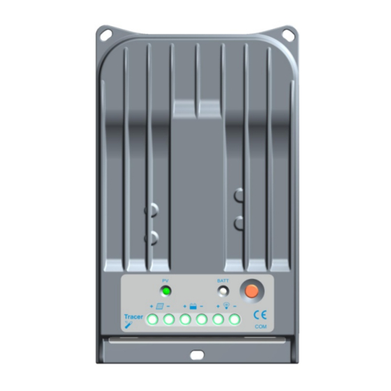
2 General Information 2.1 Overview Thank you for selecting the Tracer-BN series controller which represents advanced technology of our company. The features are listed below: ·12V/24V automatic identify or user-defined working voltage. ·Excellent heat dissipation. Using the integration of cast aluminum radiator shell, the controller can be natural cooling. - Page 6 Figure 2-1 Tracer-BN Series Characteristics 1 – Heat Sink Cast aluminum heat sink to dissipate controller heat. 2 – Charging LED Indicator Indicate that the battery is charging or not.
-
Page 7: Optional Accessories
4. USB To RS-485 converter (Model:CC-USB-RS485-150U) USB To RS-485 converter is used to monitor each controller on the network using EPsolar Station PC software and update the firmware. The length of cable is 1.5m. The CC-USB-RS485-150U connects to theRS-485 Port (9th) on the controller. -
Page 8: Installation Instructions
3 Installation Instructions 3.1 General Installation Notes •Be very careful when working with batteries. Wear eye protection. Have fresh water available to wash and clean any contact with battery acid. •Uses insulated tools and avoid placing metal objects near the batteries. •Explosive battery gasses may be present during charging. -
Page 9: Mounting
3.2 Mounting 1. Connect components to the charge controller in the sequence as shown above and pay much attention to the “+” (Red) and “-” (Black). 2. After installation, power the battery and check the battery indicator on the controller, it will be green. -
Page 10: Operation
4 Operation 4.1 MPPT Technology The Tracer-BN series utilizes Maximum Power Point Tracking technology to extract maximum power from the solar module (s). The tracking algorithm is fully automatic and does not require user adjustment, Tracer-BN series technology will track the array maximum power point voltage (Vmp) as it varies with weather conditions, ensuring that maximum power is harvested from the array through the course of the day. -
Page 11: Battery Charging Information
Current VS. Voltage in 12V system Output power in 12V system Tracer Maximum Typical Battery Maximum Power Voltage Range Point Power Traditional Point Controller Operating Range Figure 4-1 Nominal 12V Solar Module I-V curve and output power graph The array Vmp is the voltage where the product of current and voltage (Amps×Volts) is greatest, which falls on the “knee”... - Page 12 Figure 4-2 Tracer-BN series MPPT charging algorithm ·Bulk Charge In this stage, the battery voltage has not yet reached boost voltage and 100% of available solar power is used to recharge the battery. ·Boost Charge When the battery has recharged to the Boost voltage setpoint, constant-voltage regulation is used to prevent heating and excessive battery gassing.
- Page 13 maintain the battery at the Float setpoint. Should the battery voltage remains below the boost reconnect charging voltage, the controller will exit Float stage and return to Bulk charging. ·Equalize WARNING: Risk of explosion! Equalizing flooded battery can produce explosive gases, so well ventilation of battery box is necessary.
-
Page 14: Led Indications
4.3 LED Indications Charging Indicator Battery Indicator • Charging Indicator Charging LED indicator Table4-1 Indicator Status Green blink Charging Green steady OFF No charging • Battery Indicator Battery LED indicator Table 4-2 Indicator Status Green steady ON Normal Green slow blink Full Orange steady ON Under voltage warning... -
Page 15: Setting Operation
4.4 Setting Operation Three methods to configure the controller: 1–Remote meter, MT50/MT100 (Use standard twisted net cable, model: CC-RS485-RS485-200U-MT). 2–Super parameter programmer, SPP-01(Use standard twisted net cable, model: CC-RS485-RS485-200U). One-key easily configure and apply to batch setting. (Use 3–PC monitoring setting software “Solar Station Monitor” USB to RS485 converter cable with model: CC-USB-RS485-150U. - Page 16 WARNING: Do not use the standard twisted-net cable to connect the device and PC net interface, or the permanent damage will occur. •Load Set Mode .M anual Control (default) .Light ON/ Off .Light ON+ Timer .Time Control •Battery Type .Gel 2 .Sealed(default) 3....
-
Page 17: Protections, Troubleshooting And Maintenance
5 Protections, Troubleshooting and Maintenance 5.1 Protection ·PV Array Short Circuit When PV short circuit occurs, the controller will stop charging. Clear it to resume normal operation. ·PV Overvoltage If PV voltage is larger than maximum input open voltage 150V, PV will remain disconnected and warning until the voltage falls safely below 145V. -
Page 18: Troubleshooting
discharging at the default temperature 25℃ to prevent the battery damaged from overcharging or over discharged. ·Over Temperature Protection If the temperature of the controller heat sinks exceeds 85℃, the controller will automatically start the overheating protection and recover below 75℃ . 5.2 Troubleshooting Trouble Shooting Table 5-1... -
Page 19: Maintenance
NOTE: If all the led are off, please check the voltage of battery. At least 9V voltage to activate the controller. NOTE: If the charging led is steady off without miswire, check the PV input voltage which should be higher than battery’s. 5.3 Maintenance The following inspections and maintenance tasks are recommended at least two times per year for best performance. -
Page 20: Warranty
6 Warranty The Tracer-BN Series charge controller is warranted to be free from defects for a period of TWO (2) years from the date of shipment to the original end user. • Claim Procedure: Before requesting warranty service, check the Operation Manual to be certain that there is a problem with the controller. -
Page 21: Technical Specifications
Tracer4215BN Tracer1215BN Tracer2215BN Rated discharge current Tracer3215BN Tracer4215BN Maximum battery voltage Max. solar input voltage 150VDC Tracer1215BN 130W(12V) 260W(24V) Tracer2215BN 260W(12V) 520W(24V) Max. PV input power Tracer3215BN 390W(12V) 780W(24V) Tracer4215BN 520W(12V) 1040W(24V) ≤50mA(12V) ≤27mA(24V) Self-consumption* ≤0.26V Charge circuit voltage drop ≤0.15V... - Page 22 • Control Parameters Table 7-2 Battery charging setting Sealed Flooded User Over Voltage Disconnect 16.0V 16.0V 16.0V 9~17V Voltage Charging Limit Voltage 15.0V 15.0V 15.0V 9~17V Over Voltage Reconnect 15.0V 15.0V 15.0V 9~17V Voltage Equalize Charging Voltage —— 14.6V 14.8V 9~17V Boost Charging Voltage 14.2V...
- Page 23 Storage temperature -35℃ to +80℃ range ≤95%(NC) Humidity range Enclosure IP30 ≤3000 m Altitude • Mechanical Parameters (Tracer1215BN) Table 7-4 Mechanical Parameter Dimension 196mm x 117.8mm x 36mm Mounting dimension Detail in dimensions drawing Φ4.7 Mounting hole size Power cable Weight 0.9kg...
- Page 24 • Mechanical Parameters (Tracer3215BN) Table 7-6 Mechanical Parameter Dimension 280.7mm x 159.7mm x 60mm Mounting dimension Detail in dimensions drawing Φ4.7 Mounting hole size Power cable 16mm Weight 2.3kg • Mechanical Parameters (Tracer4215BN) Table 7-7 Mechanical Parameter Dimension 302.5mm x 182.7mm x 63.5mm Mounting dimension Detail in dimensions drawing Φ4.7...
- Page 25 PV Power — Conversion Efficiency Curve Tracer1215BN Illumination Intensity: 1000W/m Temp: 25ºC Solar Module MPP Voltage(16.5V, 34V, 66V) / Nominal System Voltage(12V) Solar Module MPP Voltage(34V, 66V, 98V) / Nominal System Voltage(24V) 24V Conversion Efficiency Curves Charging Power(W)
- Page 26 Tracer2215BN Illumination Intensity: 1000W/ Temp: 25ºC Solar Module MPP Voltage(16.5V, 33V, 66V) / Nominal System Voltage(12V) Solar Module MPP Voltage(33V, 66V, 98V) / Nominal System Voltage(24V) 24V Conversion Efficiency Curves Charging Power(W)
- Page 27 Tracer3215BN Illumination Intensity: 1000W/ Temp: 25ºC Solar Module MPP Voltage(16.5V, 33V, 66V) / Nominal System Voltage(12V) 12V Conversion Efficiency Curves 16.5V Charging Power(W) Solar Module MPP Voltage(33V, 66V, 98V) / Nominal System Voltage(24V) 24V Conversion Efficiency Curves Charging Power(W)
- Page 28 Tracer4215BN Illumination Intensity: 1000W/ Temp: 25ºC Solar Module MPP Voltage(16.5V, 33V, 66V) / Nominal System Voltage(12V) Solar Module MPP Voltage(33V, 66V, 98V) / Nominal System Voltage(24V)
- Page 29 Tracer1215BN Dimensions (mm)
- Page 30 Tracer2215BN Dimensions (mm)
- Page 31 Tracer3215BN Dimensions (mm)
- Page 32 Tracer4215BN Dimensions (mm)
- Page 35 Version number: V1.7...
- Page 36 BEIJING EPSOLAR TECHNOLOGY CO., LTD. Tel: +86-10-82894112 / 82894962 Fax: +86-10-82894882 E-mail: info@epsolarpv.com Website: http://www.epsolarpv.com/...
Need help?
Do you have a question about the Tracer1215BN and is the answer not in the manual?
Questions and answers