Table of Contents

Related Manuals for Univex SRM80+


Summary of Contents for Univex SRM80+
- Page 1 SRM80+ PLANETARY MIXER MAINTENANCE & PARTS MANUAL Persons under age 18 are not permitted to operate or have accessibility to operate this equipment per U.S. Dept. Of Labor Employment Standards Administration Fact Sheet No. ESA913. SRM60/80 SERVICE REV A...
-
Page 2: Table Of Contents
TABLE OF CONTENTS DESCRIPTION PAGE TABLE OF CONTENTS......................I LIST OF ILLUSTRATIONS.....................II TROUBLE SHOOTING GUIDE ...................1.1 MECHANICS MAINTENANCE CVT BELTS........................2.1 BELT REPLACEMENT....................2.2 BELT ADJUSTMENT ......................2.2 MOTOR ..........................2.4 BOWL LIFT ADJUSTMENT...................2.4 LUBRICATION........................2.5 REMOVAL OF TOP COVER ..................2.6 TRANSMISSION REMOVAL ........................3.1 TRANSMISSION PARTS LIST..................3.3 BEATER HEAD ASSEMBLY..................3.5 BEATER HEAD PARTS LIST ..................3.6 POWER TAKE-OFF ASSEMBLY...................3.7... -
Page 3: List Of Illustrations
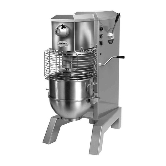
LIST OF ILLUSTRATIONS DESCRIPTION PAGE FIGURE 1 OVERALL VIEW OF MIXER..................III FIGURE 2 CUTAWAY VIEW OF MIXER ...................IV FIGURE 3 LUBRICATION DIAGRAM..................2.5 FIGURE 4 TRANSMISSION ASSEMBLY .................3.4 FIGURE 5 BEATER HEAD ASSEMBLY..................3.6 FIGURE 6 POWER TAKE-OFF ASSEMBLY (PTO)..............3.8 FIGURE 7 INPUT ASSEMBLY ....................3.10 FIGURE 8 VERTICAL SHAFT ASSEMBLY................3.12... - Page 4 OVERALL VIEW OF MIXER FIGURE 1 1. BEATER HEAD 12. START BUTTON 2. CHUTE 13. STOP BUTTON 3. SAFETY RING ASSEMBLY 14. BOWL LIFT HANDLE 4. MAGNET 15. REAR ACCESS PANEL 5. No.12 HUB 16. CAP 6. THUMB SCREW 17. BOWL SUPPORT 7.
- Page 5 CUTAWAY VIEW OF MIXER FIGURE 2 Page IV...
-
Page 6: Trouble Shooting Guide
SRM60+ / SRM80+ TROUBLESHOOTING GUIDE TROUBLE POSSIBLE CAUSE REMEDY 1. Mixer will not operate. 1.1 Timer not turned on. 1.1 Turn timer on. 1.2 Burned switch contacts. 1.2 Replace. 1.3 Electrical service down. 1.3 Check electrical service. Replace fuse or reset circuit breaker if necessary. - Page 7 SRM60+/ SRM80+ TROUBLESHOOTING GUIDE (CONTINUED) 7. Attachments contact 7.1 Dented bowl. 7.1 Remove dents or replace bowl. side of bowl 7.2 Insufficient clearance 7.2 Adjust bowl height. between bottom of bowl and beater. 8. Excessive noise 8.1 Gears need to be repacked 8.1 Locate source by inspection with grease.
-
Page 8: Mechanics Maintenance
MECHANICS MAINTENANCE Every six months a mechanic should perform the following inspection and maintenance. CVT BELT: 1. WARNING: Start the mixer and adjust the speed control lever (Figure 1 [9]) to the lowest speed (speed 1). Stop the mixer. FOR SAFETY, DISCONNECT THE ELECTRICAL POWER SUPPLY CORD. 2. -
Page 9: Belt Replacement
BELT REPLACEMENT: 1. Run the mixer and shift to first speed “1” and shut the mixer off. FOR SAFETY, DISCONNECT THE ELECTRICAL POWER SUPPLY CORD. NOTE: MIXERS WITH POWER BOWL LIFT: Loosen the four 5/16-18 Kep nuts (Figure 12 [11]) and slide the bracket (Figure 12 [16]) all the way toward the front of the mixer housing and remove the chain (Figure 12 [10]). - Page 10 d. Start the mixer and shift the speed control to speed 4 and stop the mixer. Check the position of the belt on the lower vari-speed pulley. The belt should be flush to 1/16 inch below the outer edge of the pulley flanges. e.
-
Page 11: Motor
MOTOR: Check the motor (Figure 14 [4]) for overheating, noise and excessive end play of the shaft. Replace the motor if it is found to be defective with a factory approved motor. Replacing the motor with a nonapproved motor will void the warranty. 3. -
Page 12: Lubrication
LUBRICATION 1. The lubrication instructions are listed in Figure 3. 2. Remove the top cover per Removal Of Top Cover on page 2.6 and remove the rear access panel. 3. In order to service the gearbox, it will be necessary to remove the transmission cover. A thin blade putty knife will prove helpful in separating the silicone sealant between the cover and the gearbox. -
Page 13: Removal Of Top Cover
MECHANICS MAINTENANCE REMOVAL OF TOP COVER a. The top cover (Figure 15 [4]) must be removed to perform maintenance operations on the mixer. It is secured by a spring clip at its front end and a screw in back. Before removing the top cover DISCONNECT THE ELECTRICAL POWER CORD. -
Page 14: Transmission
REPAIR INSTRUCTIONS TRANSMISSION: (Figure 4) REMOVAL: 1. Run the mixer and shift to low speed (speed 1) and shut the mixer off. 2. WARING: DISCONNECT THE ELECTRICAL POWER SUPPLY CORD. 3. Remove the drain plug (Figure 4 [18]) and drain the transmission oil. 4. - Page 15 2 Set Screws Upper Vari-Speed Pulley Oil Drain Plug Transmission Mounting Bolts Page 3.2...
- Page 16 TRANSMISSION ASSEMBLY FIGURE 4 ILLUS. No. PART No. DESCRIPTION QTY. 1064035 Transmission Assembly with shafts (SRM 60) 1080500 Transmission Assembly with shafts (SRM 80) 1065009A Transmission Housing Assembly & Vertical Shaft Assembly (SRM60) 1080502A Transmission Housing Assembly & Vertical Shaft Assembly (SRM80) Oil Tube Set Screw #8-32 x 1/4 cup point 1065000...
- Page 17 TRANSMISSION ASSEMBLY FIGURE 4 Page 3.4...
- Page 18 Beater head assembly: (Figure 5) 1. Remove the 1/2-20 hex head cap screw (Figure 5 [14]), (left hand thread), and washer [13] and remove the beater head assembly using the two jack screws (Figure 5 [12]) if necessary. 2. Remove the drive pin (Figure 5 [3]) with the tool T6012. 3.
-
Page 19: Beater Head Assembly
BEATER HEAD ASSEMBLY FIGURE 5 ILLUS. No. PART No. DESCRIPTION QTY. 1064075 Beater Head Assembly Beater Head Housing Beater Head Shaft 1200310 Dowel Pin 1/2 x 2 Bearing Spacer Bearing Retaining Ring, Internal N5002-281 Seal 1061003A Pinion Gear Assembly Retaining Ring, External 5101-137 Socket Head Set Screw 5/16-18 x 1-3/4 1064075A Beater Head Hardware Kit... - Page 20 POWER TAKE-OFF ASSEMBLY: (Figure 6) 1. Remove the retaining ring Figure 6 [14]) from the end of the PTO shaft [12] and remove the helical gear [13] from the PTO shaft. 2. Remove the three 5/16-18 hex head cap screws [7], Washers [6],. Thread two of the 5/16-18 screws into the threaded holes in the transmission housing and turning the screws alternately, jack the power take-off assembly from the transmission housing.
-
Page 21: Power Take-Off Assembly
POWER TAKE-OFF ASSEMBLY FIGURE 6 ILLUS. No. PART No. DESCRIPTION QTY. 1065002 Power Take-Off Assembly (SRM60) 1080600 Power Take-Off Assembly (SRM80) Cover Slotted Flat Head Screw Power Take-Off Washer 8800012 Adapter Power Take-Off Housing Lock Washer 5/16 Hex Head Cap Screw 5/16-18 x 1 Seal Bearing Retaining Ring, Internal... - Page 22 INPUT ASSEMBLY: (Figure 7) 1. Remove the four 5/16-18 hex head cap screws (Figure 7 [8]) and the washers [7] securing the input assembly to the transmission housing. 2. Thread two of the 5/16-18 hex head screws into the two threaded jacking screw holes in the input housing flange.
-
Page 23: Input Assembly
INPUT ASSEMBLY FIGURE 7 ILLUS. No. PART No. DESCRIPTION QTY. 106503A Input Shaft Assembly Retaining Ring, External 5101-118 Bearing Input Gear/Shaft Seal Retaining Ring Internal N5002-244 Input Housing Lock Washer 5/16 Hex Head Cap Screw 5/16-18 x 3/4 Sleeve Page 3.10... - Page 24 VERTICAL SHAFT ASSEMBLY: (Figure 8) 1. Remove the beater head assembly per the instructions on page 3.5. 2. Remove the power take-off assembly per the instructions on page 3.7. 3. Remove the key (Figure 8 [7]), retaining ring [1], bevel gear [2] and key [5]. 4.
- Page 25 VERTICAL SHAFT ASSEMBLY FIGURE 8 ILLUS. No. PART No. DESCRIPTION QTY. Retaining Ring, External 5101-137 1064420A Bevel Gear Set (SRM60) 1080016A Bevel Gear Set (SRM80) Bearing Retaining Ring, Internal N5002-281 Vertical Shaft Seal Bearing Page 3.12...
- Page 26 TRANSMISSION REASSEMBLY: 1. Clean all components except the bearings with safety approved cleaning solvent. Inspect all components for defects and replace those found to be defective. NOTE: All gears should be replaced as sets. 2. If any shafts have become slightly scored during the disassembly process, polish the shafts with fine machinist’s crocus cloth.
-
Page 27: Vertical Shaft Assembly
TRANSMISSION & SHAFTS ASSEMBLY FIGURE 9 Transmission Cover Helical Gear Bevel Gear Input Shaft Power Take-Off Assembly Assembly (PTO) Transmission Housing Assembly Vertical Shaft Assembly Beater Head Assembly Page 3.14... - Page 28 BOWL SUPPORT (Figure 10) BOWL SUPPORT REMOVAL: 1. WARING: DISCONNECT THE ELECTRICAL POWER SUPPLY CORD. 2. Remove the mixer top cover (Figure 15 [4]) per section 2, Mechanics Maintenance “REMOVAL OF TOP COVER” instructions on page 2.6. 3. Remove the rear access panel (Figure 15 [5]). 4.
- Page 29 Phillips Pan Head Screws Ground Screw Starter Motor Leads 1/2-20 Hex Head Screws Fixed Cover Slide Cover Page 4.2...
-
Page 30: Bowl Support Assembly
BOWL SUPPORT ASSEMBLY FIGURE 10 ILLUS. No. PART No. DESCRIPTION QTY. 1065006 Bowl Support Assembly (SRM60) 1080503 Bowl Support Assembly (SRM80) 1061028 Bowl Support (SRM60) 1080028 Bowl Support (SRM80) 1064454 Bowl Pin(SRM60) 1080030A Bowl Pin Kit (SRM80) 1064322A Bowl Clamp Assembly (SRM60) 1064322A Bowl Clamp Assembly (SRM80) Belleville Washer... - Page 31 BOWL SUPPORT ASSEMBLY FIGURE 10 Page 4.4...
- Page 32 BOWL LIFT SLIDE & FRAME (Figure 11) BOWL LIFT SLIDE & FRAME REMOVAL: 1. WARING: DISCONNECT THE ELECTRICAL POWER SUPPLY CORD. 2. Remove the mixer top cover (Figure 15 [4]) per section 2, Mechanics Maintenance “REMOVAL OF TOP COVER” instructions on page 2.6. 3.
- Page 33 BOWL LIFT SLIDE & FRAME INSTALLATION: (continued) 16. Place the thrust washer [8] and then the miter gear [11] on the lead screw. Drive the roll pin into the miter gear and through the lead screw. 17. Push the slide and lead screw down as far as it will go. Slide the collar [12] and thrust washer [8] up against the slide frame and tighten the two set screws in the collar against the flats on the lead screw.
-
Page 34: Bowl Lift Slide & Frame Assembly
BOWL LIFT SLIDE & FRAME ASSEMBLY FIGURE 11 ILLUS. No. PART No. DESCRIPTION QTY. 1065008 Bowl Lift Slide and Frame Assembly 1080025A Bowl Lift Handle Assembly Collar with Set Screw Thrust Washer (Bronze) 1064452A Yoke Assembly Hex Head Cap Screw 5/16-18 x 1-1/4 Lock Washer 5/16 Flat Washer 5/16 1062217A... - Page 35 BOWL LIFT SLIDE & FRAME ASSEMBLY FIGURE 11 Miter Gear with Set Screw This thrust washer Miter Gear is different than with Roll Pin item 8 Lead Screw Flats Slide Frame switch Plate Bowl Lift Safety Switch Floating Nut Retainer Plate Slide Assembly Page 5.4...
-
Page 36: Mixer Housing
POWER BOWL LIFT SLIDE & FRAME (Figure 12) POWER BOWL LIFT SLIDE & FRAME REMOVAL: 1. WARING: DISCONNECT THE ELECTRICAL POWER SUPPLY CORD. 2. Remove the mixer top cover (Figure 15 [4]) per section 2, Mechanics Maintenance “REMOVAL OF TOP COVER” instructions on page 2.6. 3. - Page 37 POWER BOWL LIFT SLIDE & FRAME INSTALLATION: 17. Grease the sliding surfaces of the slide and frame. See lubrication instructions on page 2.5. 18. Screw the lead screw into the floating nut and push the slide to the bottom of the slide frame so that the lead screw does not protrude through the hole in the frame.
- Page 38 POWER BOWL LIFT SLIDE & FRAME INSTALLATION (CONTINUED): 33. Connect the power supply cord and raise and lower the bowl be turning the selector switch. The mechanism should run freely. 34. raise the bowl all the way. Check the clearance between the bottom of the bowl and the batter beater.
- Page 39 Drive belt Chain 5/16-18 Kep nuts. Bowl lift motor bracket Bowl lift motor Page 6.4...
- Page 40 POWER BOWL LIFT SLIDE & FRAME ASSEMBLY FIGURE 12 ILLUS. No. PART No. DESCRIPTION QTY. 1067004A Power Bowl Lift Slide and Frame Assembly Lock Washer 3/8 Hex Head Cap Screw 3/8-16 x 1 1067025A Power Bowl Lift Lead Screw Assembly 1067010 Gearbox 1067014A...
- Page 41 POWER BOWL LIFT SLIDE & FRAME ASSEMBLY FIGURE 12 Lead Screw Flats Retainer Plate Slide UP Limit Switch Slide Frame Slide Assembly Slide Down Limit Switch Page 6.6...
- Page 42 SPEED CONTROL ASSEMBLY (Figure13) REMOVAL: 1. WARING: DISCONNECT THE ELECTRICAL POWER SUPPLY CORD. 2. Remove the mixer top cover (Figure 15 [4]) per section 2, Mechanics Maintenance “REMOVAL OF TOP COVER” instructions on page 2.6. 3. Remove the rear access panel (Figure 15 [5]). 4.
- Page 43 Speed control Speed control bearing bracket locating block Spring Speed control bearing (note orientation) Speed control detent housing Strap Speed control lever Roll pin Page 7.2...
- Page 44 INSTALLATION: 16. Install the speed control bearing [11] in the speed control bracket. Note that the bearing mounts be- hind the bracket on the 60 quart and in front of the bracket on the 80 quart mixer. The longer screw goes in the hole toward the front of the mixer.
- Page 45 Speed control bearing bracket Speed control bearing (note mounting orientation) 60 quart mixer speed control assembly Speed control bearing (note mounting orientation) Speed control bearing bracket 80 quart mixer speed control assembly Speed control locating block Ball, Spring and set screw Detent housing Spring Strap...
- Page 46 SPEED CONTROL ASSEMBLY FIGURE 13 ILLUS. No. PART No. DESCRIPTION QTY. 1065005 Speed Control Assembly (SRM60) 1080506 Speed Control Assembly (SRM80) 1064435A Speed Control Lever Assembly Roll Pin 1/4 x 3 Strap Flat Washer 3/8 Flat Washer 5/16 Kep Nut 5/16-18 Socket Head Set Screw 5/16-24 x 1-1/8 Speed Control Shaft 1064439...
- Page 47 SPEED CONTROL ASSEMBLY FIGURE 13 SRM60 SRM80 Page 7.6...
- Page 48 DRIVE ASSEMBLY (Figure 14) DISASSEMBLY 1. WARING: DISCONNECT THE ELECTRICAL POWER SUPPLY CORD. 2. Remove the mixer top cover (Figure 15 [4]) per section 2, Mechanics Maintenance “REMOVAL OF TOP COVER” instructions on page 2.6. 3. Remove the rear access panel (Figure 15 [5]). 4.
- Page 49 DRIVE ASSEMBLY FIGURE 14 ILLUS. No. PART No. DESCRIPTION QTY. 1064504 Lower Vari-Speed Pulley 1064503 Upper Vari-Speed Pulley 1064505 Drive Belt (SRM60) 1080035 Drive Belt (SRM80) 1064520 Motor, 3HP, 208-240V, 60HZ, 1PH 1064522 Motor, 3HP, 208-240/460V, 60HZ, 3PH 1064521 Motor, 3HP, 220-240V, 50HZ, 1PH 1064523 Motor, 3HP, 220/380/440V, 50HZ, 3PH 1064524...
- Page 50 HOUSING ASSEMBLY (Figure 15) The remaining parts which have not been discussed pertain to electrical components and the mixer housing. Figures 15, 16A, 16B, 16C, 16D, 16E, and 16F should provide adequate guidance for the disassembly and reassembly of these parts. MIXER HOUSING ASSEMBLY FIGURE 15 ILLUS.
- Page 51 MIXER HOUSING ASSEMBLY FIGURE 15 Page 9.2...
- Page 52 ELECTRICAL INSTALLATION INSTRUCTIONS FOR THREE PHASE MIXERS NOTE: Ground Stud 3 phase mixers are shipped with an unattached power supply cord. IMPORTANT: POWER SUPPLY CORD INSTALLATION AND Power Cord ELECTRICAL CONNECTION OF THESE MIXERS (shipped MUST BE MADE BY A QUALIFIED, LICENSED with mixer) ELECTRICIAN FOLLOWING ALL LOCAL AND NATIONAL ELECTRICAL CODES.
- Page 53 SCHEMATIC 208-230V, 60HZ, 1PH 220-240V, 50HZ, 1PH FIGURE 16A IMPORTANT: Before making electrical connections, check the specifications on the data plate, (located on the rear access panel), to assure they agree with those of your electrical service. WARNING: Whenever maintenance is being performed or whenever the top cover or rear access panel have been removed, DISCONNECT the electrical power cord and place a tag on it indicating the mixer is being worked on.
- Page 54 SCHEMATIC 208-230V, 60HZ, 3PH 220-240V, 50HZ, 3PH FIGURE 16B IMPORTANT: Before making electrical connections, check the specifications on the data plate, (located on the rear access panel), to assure they agree with those of your electrical service. WARNING: Whenever maintenance is being performed or whenever the top cover or rear access panel have been removed, DISCONNECT the electrical power cord and place a tag on it indicating the mixer is being worked on.
- Page 55 SCHEMATIC 460V, 60HZ, 3PH 380-400V 50HZ, 3PH FIGURE 16C IMPORTANT: Before making electrical connections, check the specifications on the data plate, (located on the rear access panel), to assure they agree with those of your electrical service. WARNING: Whenever maintenance is being performed or whenever the top cover or rear access panel have been removed, DISCONNECT the electrical power cord and place a tag on it indicating the mixer is being worked on.
- Page 56 MIXER WITH POWER BOWL LIFT SCHEMATIC 208-230V, 60HZ, 1PH 220-240V 50HZ, 1PH FIGURE 16D Page 10.5...
- Page 57 MIXER WITH POWER BOWL LIFT SCHEMATIC 208-230V, 60HZ, 1PH 220-240V 50HZ, 1PH FIGURE 16D Page 10.6...
- Page 58 MIXER WITH POWER BOWL LIFT SCHEMATIC 208-230V, 60HZ, 3PH 220-240V 50HZ, 3PH FIGURE 16E Page 10.7...
- Page 59 MIXER WITH POWER BOWL LIFT SCHEMATIC 208-230V, 60HZ, 3PH 220-240V 50HZ, 3PH FIGURE 16E Page 10.8...
- Page 60 MIXER WITH POWER BOWL LIFT SCHEMATIC 460V, 60HZ, 3PH 380V 50HZ, 3PH FIGURE 16F Page 10.9...
- Page 61 MIXER WITH POWER BOWL LIFT SCHEMATIC 460V, 60HZ, 3PH 380V 50HZ, 3PH FIGURE 16F Page 10.10...
- Page 62 3 Old Rockingham Road, Salem, N.H. 03079-2140 Telephone -603-893-6191 Fax 1-603-893-1249 TOLL FREE ORDERING FAX 1-800-356-5614...
Need help?
Do you have a question about the SRM80+ and is the answer not in the manual?
Questions and answers