Table of Contents
Advertisement
Quick Links
1000 W/ R-15 AM
SERVICING ................................................................................................................. INSIDE FRONT COVER
CAUTION, MICROWAVE RADIATION ................................................................................. Indside front cover
SERVICING ...................................................................................................................................................... 2
PRODUCT SPECIFICATIONS .......................................................................................................................... 5
GENERAL INFORMATION ................................................................................................................................ 5
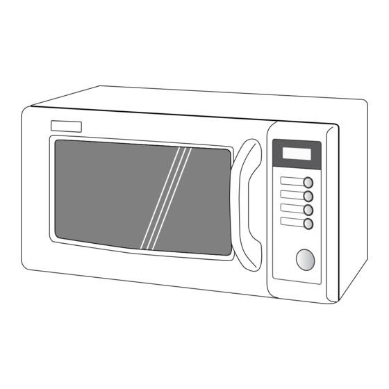
APPEARANCE VIEW ....................................................................................................................................... 6
OPERATION SEQUENCE ................................................................................................................................. 7
FUNCTION OF IMPORTANT COMPONENTS ................................................................................................ 8
TROUBLESHOOTING GUIDE .......................................................................................................................... 9
TEST PROCEDURE ....................................................................................................................................... 10
CONTROL PANEL ASSEMBLY ..................................................................................................................... 15
COMPONENT REPLACEMENT AND ADJUSTMENT PROCEDURE ........................................................... 19
MICROWAVE MEASUREMENT .................................................................................................................... 25
TEST DATA AT A GLANCE ........................................................................................................................... 25
WIRING DIAGRAM ......................................................................................................................................... 26
PICTORIAL DIAGRAM ................................................................................................................................... 27
CPU UNIT CIRCUIT ........................................................................................................................................ 28
PRINTED WIRING BOARD ............................................................................................................................. 29
PARTS LIST ................................................................................................................................................... 30
SERVICE MANUAL
MODEL
In interests of user-safety the oven should be restored to its
original condition and only parts identical to those specified
should be used.
TABLE OF CONTENTS
SHARP CORPORATION
COMMERCIAL
MICROWAVE OVEN
R-15AM
R-15AM
S0314R15AMPH/
Page
Advertisement
Table of Contents

Related Manuals for Sharp R-15AM


Summary of Contents for Sharp R-15AM
-
Page 1: Table Of Contents
R-15AM SERVICE MANUAL S0314R15AMPH/ COMMERCIAL MICROWAVE OVEN 1000 W/ R-15 AM R-15AM MODEL In interests of user-safety the oven should be restored to its original condition and only parts identical to those specified should be used. TABLE OF CONTENTS Page SERVICING ......................... -
Page 2: Microwave Radiation
R-15AM CAUTION MICROWAVE RADIATION Personnel should not be exposed to the microwave energy which may radiate from the magnetron or other microwave generating devices if it is improperly used or connected. All input and output microwave connections, waveguides, flanges and gaskets must be secured. -
Page 3: Caution, Microwave Radiation
MICROWAVE OVEN R-15AM GENERAL INFORMATION GENERAL IMPORTANT INFORMATION This Manual has been prepared to provide Sharp Corp. Service engineers with Operation and Service Information. APPEARANCE VIEW It is recommended that service engineers carefully study the entire text of this manual, so they will be qualified to render satisfactory customer service. -
Page 4: Servicing
Sharp beveelt ten sterkste aan dat, voor zover mogelijk, defecten worden opgespoord wanneer de stekker uit het Wanneer alle reparaties zijn uitgevoerd en de oven weer in stopcontact is gehaald. - Page 5 är kallt utför Du 3 steg kontroller och kontrollerar anslutningarna till varje enskild komponent på nytt. Sharp rekommenderar att felsökning sker med strömmen fränkopplad. Ibland kan det var nödvändigt att koppla på När all service är klar och ugnen ihopskruvad skall ugnens strömmen efter det att höljet avlägsnats, utför da 3 Steg...
- Page 6 Sharp raccomanda, nei limiti del possibile, che la ricerca dei guasti avvenga in assenza di alimentazione elettrica. In alcuni casi tuttavia, può essere necessario alimentare Dopo aver portato a termine le operazioni di manutenzione l'apparecchio dopo aver rimosso la scatola esterna.
-
Page 7: Product Specifications
R-15AM PRODUCT DESCRIPTION SPECIFICATION ITEM DESCRIPTION Power Requirements 230 Volts 50 Hertz Single phase, 3 wire earthed Power Comsumption 1.55 KW Approx. 7.0 A Power Output 1000 W nominal of RF microwave energy (measured by method of IEC 60705) Operating frequency 2450 MHz... -
Page 8: Appearance View
R-15AM APPEARANCE VIEW OVEN 1. Control panel 2. Door lock openings 3. Oven lamp 4. Ceramic floor (Not removal) 5. Door hinges 6. Door 7. Door open handle 8. Safty door latches 9. Door seals and sealing surfaces 10.Cavity face plate 11.Air ventilation cover and openings... -
Page 9: Operation Sequence
R-15AM OPERATION SEQUENCE OFF CONDITION 6. MONITOR SWITCH CIRCUIT The monitor switch is mechanically controlled by the Closing the door activates the 1st. interlock switch SW1 oven door, and monitors the operation of the 1st. and 2nd. interlock relay control switch SW2. -
Page 10: Function Of Important Components
R-15AM FUNCTION OF IMPORTANT COMPONENTS DOOR OPEN MECHANISM HIGH VOLTAGE FUSE F2 0.75A The door is opened by grasping the door handle, refer to The high voltage fuse blows when the high voltage rectifier Figure D-1. or the magnetron is shorted. -
Page 11: Troubleshooting Guide
R-15AM TROUBLESHOOTING GUIDE When troubleshooting the microwave oven, it is helpful to follow the Sequence of Operation in performing the checks. Many of the possible causes of trouble will require that a specific test be performed. These tests are given a procedure letter which will be found in the “Test Procedure”... -
Page 12: Test Procedure
R-15AM TEST PROCEDURES PROCEDURE LETTER COMPONENT TEST MAGNETRON TEST NEVER TOUCH ANY PART IN THE CIRCUIT WITH YOUR HAND OR AN INSULATED TOOL WHILE THE OVEN IS IN OPERATION. CARRY OUT 3D CHECKS. Isolate the magnetron from high voltage circuit by removing all leads connected to filament terminal. - Page 13 R-15AM TEST PROCEDURES PROCEDURE LETTER COMPONENT TEST Room temperature ....................To = 21˚C Initial temperature ....................T1 = 11°C Temperature after (42 + 3) = 45 sec ..............T2 = 21°C Temperature difference Cold-Warm................ ∆T = 10˚C Measured output power The equation is “P = 100 x ∆T”...
- Page 14 R-15AM TEST PROCEDURES PROCEDURE LETTER COMPONENT TEST C. A normal capacitor shows continuity for a short time (kick) and then a resistance of about 10MΩ after it has been charged. D. A short-circuited capacitor shows continuity all the time. E. An open capacitor constantly shows a resistance about 10 MΩ because of its internal 10MΩ...
- Page 15 R-15AM TEST PROCEDURES PROCEDURE LETTER COMPONENT TEST NOISE FILTER TEST CARRY OUT 3D CHECKS. F1: FUSE F10A Disconnect the leads from the terminals of noise filter. DISCHARGE RESISTOR 680 kΩ 1/2W Using an ohmmeter, check between the terminals as described in the following table.
- Page 16 R-15AM TEST PROCEDURES PROCEDURE LETTER COMPONENT TEST g) The figure of all digits flicker. h) When touching a tact switch, the control unit does not respond. 4. Other possible problems caused by defective control unit. a) Buzzer does not sound or continues to sound.
-
Page 17: Control Panel Assembly
R-15AM TEST PROCEDURES PROCEDURE LETTER COMPONENT TEST NOTE: *At the time of these repairs, make a visual inspection of the varistor for VRS1 burning damage and examine the transformer with tester for the pres- ence of layer short circuit (check pri- mary coil resistance). - Page 18 R-15AM DESCRIPTION OF LSI The I/O signal of the LSI are detailed in the foll owing table. Pin No. Signal Description SEG21- Terminal not used. SEG23 COM1 Common data signal: COM1. Connected to LCD (Pin No. 1) COM2 Common data signal: COM2.
- Page 19 R-15AM Pin No. Signal Description Magnetron high-voltage circuit driving signal. ON/OFF time ratio in Mi- To turn on and off the cook relay (RY3). cro cooking In 100% POWER operation, the signals (a. 32second time base) hold "L" level during microwave cooking MICRO and "H"...
- Page 20 R-15AM SERVICING 1. Precautions for Handling Electronic Components B. On some models, the power supply cord between This unit uses CMOS LSI in the integral part of the the touch control panel and the oven proper is so circuits. When handling these parts, the following pre- long enough that they may be separated from each cautions should be strictly followed.
-
Page 21: Component Replacement And Adjustment Procedure
Please refer to ‘OVEN PARTS, CABINET PARTS, CONTROL PANEL PARTS, DOOR PARTS’, when carrying out any of the following removal procedures: WARNING FOR WIRING and Oven cavity. To prevent an electric shock, take the following 3) Sharp edge: manners. Bottom plate, Oven cavity, Weveguide flange, 1. Before wiring, Chassis support and other metallic plate. -
Page 22: Magnetron Removal
R-15AM 3. Disconnect the filament lead of the high voltage trans- 10. Remove one (1) screw holding the fan duct to the oven former from the high voltage capacitor. cavity rear plate. 4. Remove one (1) screw holding earth side terminal of the 11. -
Page 23: Fan Motor Replacement
R-15AM FAN MOTOR REPLACEMENT REMOVAL CAUTION: * Do not reuse the removed fan blade because the 1. CARRY OUT 3D CHECKS. hole (for shaft) may be larger than normal. 2. Remove the one (1) screw holding the noise filter to the 12.Remove the two (2) screws holding the fan motor to the... - Page 24 R-15AM 1ST. INTERLOCK SWITCH, 2ND. INTERLOCK RELAY CONTROL SWITCH AND MONITOR SWITCH REMOVAL 1. CARRY OUT 3D CHECKS. 4. Make sure that the monitor switch is operating properly 2. Remove the control panel assembly referring to "CON- and check continuity of the monitor circuit.
-
Page 25: Installation Of Ceramic Shelf
R-15AM 7. Release two (2) pins of door panel from two (2) holes NOTE: After any service to the door; of upper and lower oven hinges by lifting up. (A) Make sure that 1st. interlock switch SW1, 2nd. 8. Now, door sub assembly is free from oven cavity. - Page 26 R-15AM Oven Cavity WARNING Rear Edge Make sure that the rubber packing is not caught be- Push tween the oven door and the oven cavity front plate, to avoid possible exposure to excessive microwave en- ergy. Ceramic Front Edge Shelf...
-
Page 27: Microwave Measurement
R-15AM MICROWAVE MEASUREMENT Recommended instruments are: After adjustment of door latch switches, monitor switch NARDA 8100 and door are completed individually or collectively, the NARDA 8200 following leakage test must be performed with a survey HOLADAY HI 1500 instrument and it must be confirmed that the result meets... -
Page 28: Wiring Diagram
R-15AM SCHEMATIC NOTE: Indicates components with potential above 250 V. NOTE: CONDITION OF OVEN 1. DOOR CLOSED. APPEAR ON DISPLAY. TC2: TC1: THERMAL THERMAL NOISE FILTER CUT-OUT CUT-OUT 145˚C (MG) 125˚C (OVEN) C: CAPACITOR 1.07µF AC2300V SW2: 2ND. INTERLOCK RELAY CONTROL SWITCH SW1: 1ST. -
Page 29: Pictorial Diagram
R-15AM... -
Page 30: Cpu Unit Circuit
R-15AM... -
Page 31: Printed Wiring Board
R-15AM QKITPA018URE0 WH-2 (J3) (J5) (J7) (J8) CN - B (J10) MICRO VRS1 OL/FM /TTM CN - A Figure S-3. Printed Wiring Board... -
Page 32: Parts List
R-15AM PARTS LIST ∆ Note: The parts marked " " may cause undue microwave exposure. The parts marked "*" are used in voltage more than 250V. REF. NO. PART NO. DESCRIPTION Q'TY CODE ELECTRIC PARTS RMOTDA234WRE0 Antenna motor RC-QZA320WRZZ High voltage capacitor... - Page 33 R-15AM REF. NO. PART NO. DESCRIPTION Q'TY CODE 4-35 LANGQA556WRMZ Earth angle 4-36 PCUSUA270WRP0 Cushion DOOR PARTS ∆ 5- 1 FDORFA322WRT0 Door panel assembly 5- 2 PSHEPA649WRE0 Sealer film ∆ 5- 3 FANGKA206WRY0 Latch angle assembly 5- 4 FCOV-A005WRKZ Door case assembly...
- Page 34 R-15AM OVEN AND CABINET PARTS 4-36 4-23 7-13 4-34 4-10 7-13 7-13 4-26 4-21 7-12 4-26 4-17 4-27 4-28 4-14 4-19 4-15 7-10 7-14 4-25 4-35 4-18 7-10 4-33 7-11 4-22 4-13 4-20 7-15 7-15 4-12 4-29 4-11 4-16 4-30...
- Page 35 R-15AM CONTROL PANEL PARTS 3-2-1 DOOR PARTS 5-15 5-17 5-21 5-16 5-12 5-16 5-20 5-16 5-4-2 5-4-4 5-4-3 5-4-1 5-13 5-4-4 5-16 5-12 5-4-5 5-14 5-19 5-18 5-11 5-19 MISCELLANEOUS 5-10 Actual wire harness may be different from illustration.
-
Page 36: Packing And Accessories
R-15AM PACKING AND ACCESSORIES TOP PAD ASSEMBLY (FPADBA385WRK0) WRAP COVER (SSAKHA034WRE0) TRAY HOLDER DOOR PROTECTION SHEET (SPADFA435WRE0) (SPADPA204WRE0) CAUTION SHEET BOTTOM PAD ASSEMBLY (FPADBA386WRK0) INSTRUCTION BOOK PACKING CASE Not Replaceable Items. SPAKCE006WREZ '03SHARP CORP. (11S0.EE)
Need help?
Do you have a question about the R-15AM and is the answer not in the manual?
Questions and answers