Table of Contents
Advertisement
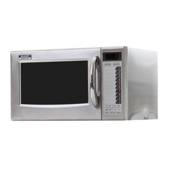
1000 W/ R-15 AT
SERVICING ................................................................................................................. INSIDE FRONT COVER
CAUTION, MICROWAVE RADIATION ................................................................................. Indside front cover
SERVICING ...................................................................................................................................................... 2
PRODUCT SPECIFICATIONS .......................................................................................................................... 5
GENERAL INFORMATION ................................................................................................................................ 5
APPEARANCE VIEW ....................................................................................................................................... 6
OPERATION SEQUENCE ................................................................................................................................. 7
FUNCTION OF IMPORTANT COMPONENTS ................................................................................................ 8
TROUBLESHOOTING GUIDE .......................................................................................................................... 9
TEST PROCEDURE ....................................................................................................................................... 10
CONTROL PANEL ASSEMBLY ..................................................................................................................... 16
WIRING DIAGRAM ......................................................................................................................................... 30
PICTORIAL DIAGRAM ................................................................................................................................... 31
CPU UNIT CIRCUIT ........................................................................................................................................ 32
PRINTED WIRING BOARD ............................................................................................................................. 33
PARTS LIST ................................................................................................................................................... 34
SERVICE MANUAL
ON
DEF
NO. X2 CHECK
MODEL
2
X
DOUBLE
EXPRES S
QUANTI TY
DEFROS T
1
11
2
12
3
13
4
14
5
15
6
16
7
17
8
18
9
19
0
20
SELEC T
TIME
STOP
CLEAR
SELEC T
POWE R
START
In interests of user-safety the oven should be restored to its
SET
CHECK
SIGNA L
original condition and only parts identical to those specified
should be used.
TABLE OF CONTENTS
SHARP CORPORATION
COMMERCIAL
MICROWAVE OVEN
R-15AT
R-15AT
S0313R15ATPH/
Page
Advertisement
Table of Contents

Related Manuals for Sharp R-15AT


Summary of Contents for Sharp R-15AT
-
Page 1: Table Of Contents
R-15AT SERVICE MANUAL S0313R15ATPH/ COMMERCIAL MICROWAVE OVEN 1000 W/ R-15 AT R-15AT NO. X2 CHECK MODEL DOUBLE EXPRES S QUANTI TY DEFROS T SELEC T TIME STOP CLEAR SELEC T POWE R START In interests of user-safety the oven should be restored to its... -
Page 2: Caution Microwave Radiation
R-15AT CAUTION MICROWAVE RADIATION Personnel should not be exposed to the microwave energy which may radiate from the magnetron or other microwave generating devices if it is improperly used or connected. All input and output microwave connections, waveguides, flanges and gaskets must be secured. -
Page 3: Servicing
MICROWAVE OVEN R-15AT GENERAL INFORMATION GENERAL IMPORTANT INFORMATION This Manual has been prepared to provide Sharp Corp. Service engineers with Operation and Service Information. APPEARANCE VIEW It is recommended that service engineers carefully study the entire text of this manual, so they will be qualified to render satisfactory customer service. -
Page 4: Servicing
Sharp beveelt ten sterkste aan dat, voor zover mogelijk, defecten worden opgespoord wanneer de stekker uit het Wanneer alle reparaties zijn uitgevoerd en de oven weer in stopcontact is gehaald. - Page 5 är kallt utför Du 3 steg kontroller och kontrollerar anslutningarna till varje enskild komponent på nytt. Sharp rekommenderar att felsökning sker med strömmen fränkopplad. Ibland kan det var nödvändigt att koppla på När all service är klar och ugnen ihopskruvad skall ugnens strömmen efter det att höljet avlägsnats, utför da 3 Steg...
- Page 6 Sharp raccomanda, nei limiti del possibile, che la ricerca dei guasti avvenga in assenza di alimentazione elettrica. In alcuni casi tuttavia, può essere necessario alimentare Dopo aver portato a termine le operazioni di manutenzione l'apparecchio dopo aver rimosso la scatola esterna.
-
Page 7: Product Description
R-15AT PRODUCT DESCRIPTION SPECIFICATION ITEM DESCRIPTION Power Requirements 230 Volts 50 Hertz Single phase, 3 wire earthed Power Comsumption 1.55 KW Approx. 7.0 A Power Output 1000 W nominal of RF microwave energy (measured by method of IEC 60705) Operating frequency 2450 MHz... -
Page 8: Appearance View
R-15AT APPEARANCE VIEW OVEN 1. Oven light 2. Ceramic shelf 3. Control panel 4. Cavity face plate 5. Door latch openings 6. Door latches 7. Door hinges 8. Door seals and sealing surfaces 9. Door handle 10.Oven door with see-through window TOUCH CONTROL PANEL 11.Air ventilation cover and openings... -
Page 9: Operation Sequence
R-15AT OPERATION SEQUENCE OFF CONDITION 6-1. When the oven door is opened during or after the cycle of a cooking program, the 2nd. interlock switch Closing the door activates the primary interlock relay SW2 and primary interlock relay control switch SW1 control switch SW1 and 2nd. -
Page 10: Function Of Important Components
R-15AT FUNCTION OF IMPORTANT COMPONENTS DOOR OPEN MECHANISM HIGH VOLTAGE FUSE F2 0.75A The door is opened by grasping the door handle, refer to The high voltage fuse blows when the high voltage rectifier Figure D-1. or the magnetron is shorted. -
Page 11: Troubleshooting Guide
R-15AT TROUBLESHOOTING GUIDE When troubleshooting the microwave oven, it is helpful to follow the Sequence of Operation in performing the checks. Many of the possible causes of trouble will require that a specific test be performed. These tests are given a procedure letter which will be found in the “Test Procedure”... - Page 12 R-15AT TEST PROCEDURES PROCEDURE LETTER COMPONENT TEST MAGNETRON TEST NEVER TOUCH ANY PART IN THE CIRCUIT WITH YOUR HAND OR AN INSULATED TOOL WHILE THE OVEN IS IN OPERATION. CARRY OUT 3D CHECKS. Isolate the magnetron from high voltage circuit by removing all leads connected to filament terminal.
- Page 13 R-15AT TEST PROCEDURES PROCEDURE LETTER COMPONENT TEST Room temperature ....................To = 21˚C Initial temperature ....................T1 = 11°C Temperature after (42 + 3) = 45 sec ..............T2 = 21°C Temperature difference Cold-Warm..............∆T1 = 10˚C Measured output power The equation is “P = 100 x ∆T”...
- Page 14 R-15AT TEST PROCEDURES PROCEDURE LETTER COMPONENT TEST C. A normal capacitor shows continuity for a short time (kick) and then a resistance of about 10MΩ after it has been charged. D. A short-circuited capacitor shows continuity all the time. E. An open capacitor constantly shows a resistance about 10 MΩ because of its internal 10MΩ...
- Page 15 R-15AT TEST PROCEDURES PROCEDURE LETTER COMPONENT TEST NOISE FILTER TEST CARRY OUT 3D CHECKS. F1: FUSE F10A DISCHARGE RESISTOR 680 kΩ 1/2W Disconnect the leads from the terminals of noise filter. Using an ohmmeter, check between the terminals as described in the following table.
- Page 16 R-15AT TEST PROCEDURES PROCEDURE LETTER COMPONENT TEST e) Wrong figure appears. f) A certain group of indicators do not light up. g) The figure of all digits flicker. 2-3 Other possible troubles caused by defective control unit. a) Buzzer does not sound or continues to sound.
- Page 17 R-15AT TEST PROCEDURES PROCEDURE LETTER COMPONENT TEST PROCEDURES TO BE TAKEN WHEN THE FOIL PATTERN ON THE PRINTED WIRING BOARD (PWB) IS OPEN To protect the electronic circuits, this model is provided with a fine foil pattern added to the input circuit on the PWB, this foil pattern acts as a fuse.
-
Page 18: Touch Control Panel Assembly
R-15AT TOUCH CONTROL PANEL ASSEMBLY OUTLINE OF TOUCH CONTROL PANEL The touch control section consists of the following units as 11) Relay Driving Circuit shown in the touch control panel circuit. This is a circuit for driving output relay by IC1 output. - Page 19 R-15AT Pin No. Signal Description AN5-AN4 Terminal to change functions according to the model. Signal in accordance with the model in operation is applied to set up its function. 9-10 AN3-AN2 Terminal not used. Input signal which communicates the door open/close information to LSI.
- Page 20 R-15AT Pin No. Signal Description RESET Auto clear terminal. Signal is input to reset the LSI to the initial state when power is supplied. Temporarily set to "L" level the moment power is supplied, at this time the LSI is reset. Thereafter set at "H"...
- Page 21 R-15AT 2-2 Memory IC (IC2) AT24C02 is a 2K-bit, serial memory, enabling CMOS to be erased/written electrically. This memory is constructed with 256 registers x 8bits, enabling individual access, read and write operations to be performed. Details of input/output signal for IC2 are as shown in the following diagram.
- Page 22 R-15AT TOUCH CONTROL PANEL SERVICING 1. Precautions for Handling Electronic Components 4) Re-install the outer case (cabinet). This unit uses CMOS LSI in the integral part of the 5) Re-connect the power supply cord after the outer circuits. When handling these parts, the following case is installed.
- Page 23 R-15AT PROCEDURE FOR CHECKING/CLEARING SERV- 3) Practice for inputting total using times (Ex. 310000 times). ICE COUNTS OF MICROWAVE OVEN ... Flashing / ... 0.1sec BUZZER The following procedure enables the servicer to obtain the total using times (cook cycles) since the microwave oven...
- Page 24 R-15AT 5) Practice for cancelling total using times and total op- DISPLAY PAUSE eration time (user and service) and all other counter. End of each stage After 10% of total cooking time is passed ... Flashing / ... 0.1sec BUZZER...
-
Page 25: Component Replacement And Adjustment Procedure
Oven lamp, Magnetron, High voltage transformer manners. and Oven cavity. 1. Before wiring, 3) Sharp edge: 1) Disconnect the power supply. Bottom plate, Oven cavity, Weveguide flange, 2) Open the door and wedge the door open. Chassis support and other metallic plate. -
Page 26: Magnetron Removal
R-15AT 4. Remove one (1) screw holding earth side terminal of the cavity rear plate. high voltage rectifier assembly. 11. Release the capacitor holder from the fan duct. 5. Disconnect high voltage fuse and terminal of high voltage 12. Remove the capacitor from the capacitor holder. -
Page 27: Antenna Motor Removal
R-15AT ANTENNA MOTOR REMOVAL 3. Disconnect the wire leads from the antenna motor and 1. Disconnect the oven from the power supply. remove the one (1) screw holding the antenna motor. 2. Remove the one (1) screw holding the base plate cover to 4. - Page 28 R-15AT PRIMARY INTERLOCK RELAY CONTROL SWITCH, 2ND. INTERLOCK SWITCH AND MONITOR SWITCH REMOVAL 1. CARRY OUT 3D CHECKS. 4. Make sure that the monitor switch is operating properly 2. Remove the control panel assembly referring to "CON- and check continuity of the monitor circuit.
-
Page 29: Installation Of Ceramic Shelf
R-15AT 7. Release two (2) pins of door panel from two (2) holes of lock relay control switch and monitor switch are upper and lower oven hinges by lifting up. operating properly. (Refer to chapter "Test Proce- 8. Now, door sub assembly is free from oven cavity. - Page 30 R-15AT Oven Cavity WARNING Rear Edge Push Make sure that the rubber packing is not caught be- tween the oven door and the oven cavity front plate, to avoid possible exposure to excessive microwave en- ergy. Ceramic Shelf Front Edge...
-
Page 31: Microwave Measurement
R-15AT MICROWAVE MEASUREMENT Recommended instruments are: After adjustment of door latch switches, monitor switch NARDA 8100 and door are completed individually or collectively, the NARDA 8200 following leakage test must be performed with a survey HOLADAY HI 1500 instrument and it must be confirmed that the result meets... - Page 32 R-15AT SCHEMATIC NOTE: Indicates components with potential above 250 V. NOTE: CONDITION OF OVEN 1. DOOR CLOSED. APPEAR ON DISPLAY. TC2: TC1: THERMAL THERMAL NOISE FILTER CUT-OUT CUT-OUT 125˚C (OVEN) 145˚C (MG) C: CAPACITOR 1.07µF AC2300V SW1: PRIMARY INTERLOCK RELAY CONTROL SWITCH SW2: 2ND.
- Page 33 R-15AT...
- Page 34 R-15AT...
-
Page 35: Printed Wiring Board
R-15AT (C83) (C82) (C81) (C80) (R91) (R90) (JJ) (R89) (R66) (C64) (JH) (R69) (R65) (R68) (R60) (C60) (R62) (C101) (C60) (J5) (JG) (JD) (R61) (J6) (JE) (R64) (R63) (C63) (CN - H) (JA) (R1) (ZD1) (R2) (R101) (14) (15) (16) -
Page 36: Parts List
R-15AT PARTS LIST ∆ Note: The parts marked " " may cause undue microwave exposure. The parts marked "*" are used in voltage more than 250V. REF. NO. PART NO. DESCRIPTION Q'TY CODE ELECTRIC PARTS RMOTDA234WRE0 Antenna motor RC-QZA320WRZZ High voltage capacitor... - Page 37 R-15AT ∆ Note: The parts marked " " may cause undue microwave exposure. The parts marked "*" are used in voltage more than 250V. REF. NO. PART NO. DESCRIPTION Q'TY CODE VRD-B12EF272J Resistor 2.7k ohm 1/4W VRD-B12EF472J Resistor 4.7k ohm...
- Page 38 R-15AT ∆ Note: The parts marked " " may cause undue microwave exposure. The parts marked "*" are used in voltage more than 250V. REF. NO. PART NO. DESCRIPTION Q'TY CODE 5-14 LANGJA020WRP0 Earth angle 5-15 PCUSUA505WRP0 Cushion 5-16 XEBSD38P08000 Screw : 3.8mm x 8mm...
- Page 39 R-15AT OVEN AND CABINET PARTS 4-23 7-13 4-34 4-10 7-13 7-13 4-26 4-21 7-12 4-26 4-17 4-27 4-28 4-14 4-19 4-15 4-35 7-10 7-14 4-25 7-11 7-10 4-18 4-33 4-22 4-13 4-20 7-15 7-15 4-12 4-29 4-11 4-16 4-30 7-11...
- Page 40 R-15AT CONTROL PANEL PARTS 3-2-3 3-2-2 DOOR PARTS 3-2-1 5-15 5-17 5-16 5-21 5-12 5-16 5-20 5-16 5-4-2 5-4-4 5-4-1 5-4-3 5-13 5-16 5-4-4 5-12 5-4-5 5-14 5-19 5-18 5-11 5-19 MISCELLANEOUS 5-10 Actual wire harness may be different from illustration.
Need help?
Do you have a question about the R-15AT and is the answer not in the manual?
Questions and answers