Viessmann VITODENS 242-F Technical Manual
Gas condensing storage combi boiler
Hide thumbs
Also See for VITODENS 242-F:
- Installation and service instructions manual (200 pages) ,
- Technical manual (112 pages) ,
- Installation and service instructions for contractors (144 pages)
Table of Contents
Advertisement
VIESMANN
Technical guide
VITODENS 222-F
Gas condensing storage combi boiler,
4.8 to 35.0 kW,
for natural gas and LPG
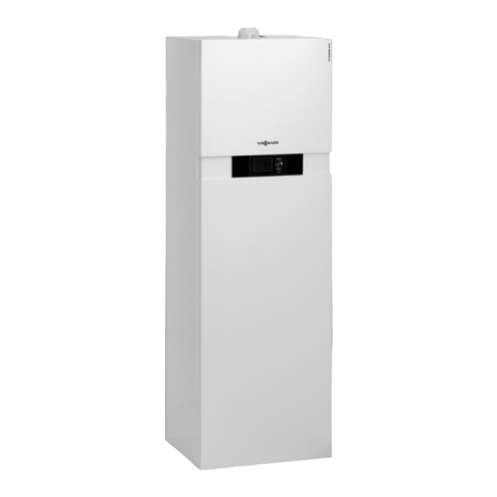
VITODENS 242-F
Compact Energy Tower for combined gas condensing/
solar thermal systems,
4.8 to 26.0 kW,
for natural gas and LPG
VITODENS 333-F
Gas condensing storage combi boiler,
3.8 to 26.0 kW,
for natural gas and LPG
5822 431 GB
5/2010
Type FS2B
Type FB2B
Type FS3B and FR3B
VITODENS
Gas condensing boiler
3.8 to 35.0 kW
Advertisement
Table of Contents

Subscribe to Our Youtube Channel
Related Manuals for Viessmann VITODENS 242-F


Summary of Contents for Viessmann VITODENS 242-F
- Page 1 VITODENS 222-F Type FS2B Gas condensing storage combi boiler, 4.8 to 35.0 kW, for natural gas and LPG VITODENS 242-F Type FB2B Compact Energy Tower for combined gas condensing/ solar thermal systems, 4.8 to 26.0 kW, for natural gas and LPG...
-
Page 2: Table Of Contents
■ Solar coverage ......................76 ■ DHW demand of residential units ................76 ■ Determining the required collector area ..............76 ■ Sizing aid for the Vitodens 242-F ................77 Control units 7.1 Vitotronic 100, type HC1A, for constant temperature operation ........81 ■... - Page 3 Index (cont.) 7.3 Accessories for the Vitotronic ..................85 ■ Allocation to control unit types .................. 85 ■ Vitotrol 100, type UTA ....................85 ■ Vitotrol 100, type UTDB .................... 86 ■ External extension H4 ....................86 ■ Vitotrol 100, type UTDB-RF ..................87 ■...
-
Page 4: Vitodens 222-F, Type Fs2B 1.1 Product Description
A) Like all Viessmann storage combi boilers, the Vitodens 222-F gas ■ Universal connection sets for individual installation flush with the wall condensing storage combi boiler takes up little space: width and depth ■... - Page 5 Vitodens 222-F, type FS2B (cont.) Accessories required (order separately) ■ Connection set (for downward connection) with premounting bracket for installation on finished walls Installation on finished walls ■ Connection set (for upward connection) for installation on finished ■ Assembly kit with mixer walls Installation on unfinished walls ■...
-
Page 6: Specification
Vitodens 222-F, type FS2B (cont.) 1.2 Specification Gas boiler, types B and C, category II 2N3P Rated output range (details to DIN EN 677) = 50/30 °C 4.8-19.0 6.5-26.0 8.8-35.0 = 80/60 °C 4.3-17.2 5.9-23.7 8.0-31.7 Rated output for DHW heating 4.3-17.2 5.9-29.3 8.0-35.0... - Page 7 Vitodens 222-F, type FS2B (cont.) Gas boiler, types B and C, category II 2N3P Rated output range (details to DIN EN 677) = 50/30 °C 4.8-19.0 6.5-26.0 8.8-35.0 = 80/60 °C 4.3-17.2 5.9-23.7 8.0-31.7 Flue gas parameters Flue gas value group to G 635/G 636 Temperature (at 30 °C return temperature) –...
- Page 8 Vitodens 222-F, type FS2B (cont.) A Heating flow R ¾ F DHW circulation R ½ (separate accessory) B DHW R ½ G Condensate drain to the back into the wall C Gas connection R ½ H Side condensate drain D Cold water R ½ K Cable entry area E Heating return R ¾...
- Page 9 Vitodens 222-F, type FS2B (cont.) Note The adjustable feet give all height measurements a tolerance of +15 mm. Two-stage heating circuit pump in the Vitodens 222-F Rated boiler output 4.8 - 26.0 8.8 - 35.0 Type VI UPSO 15-60 VI UPSO 15-70 Rated voltage Power consumption Stage 1...
- Page 10 Vitodens 222-F, type FS2B (cont.) Vitodens 222-F, 8.8 - 35.0 kW 1000 1100 1200 1300 1400 Flow rate in l/h A Stage 1 B Stage 2 C Upper operational limit Variable speed heating circuit pump in the Vitodens 222-F The integral circulation pump is a highly efficient DC pump with sub- Circulation pump VI UPM-15-70 KM stantially lower power consumption than conventional pumps.
- Page 11 Vitodens 222-F, type FS2B (cont.) Residual head of the integral circulation pump Vitodens 222-F, 4.8 - 26.0 kW 1000 1100 1200 1300 1400 Flow rate in l/h E Upper operational limit Curve Circulation pump rate Setting code address "E6" 30 % E6:030 50 % E6:050...
- Page 12 Vitodens 222-F, type FS2B (cont.) Vitodens 222-F, 8.8 - 35.0 kW 900 1000 1100 1200 1300 1400 1500 Flow rate in l/h G Upper operational limit Curve Circulation pump rate Setting code address "E6" 30 % E6:030 50 % E6:050 60 % E6:060 70 %...
-
Page 13: Vitodens 242-F, Type Fb2B 2.1 Product Description
A convenient DHW supply is ensured by the 170 l dual mode DHW ■ The programming unit part of the control unit can also be fitted on a cylinder. For ease of handling, the Vitodens 242-F can be transported wall mounting base (accessory) in two parts. - Page 14 Vitodens 242-F, type FB2B (cont.) Accessories required (order separately) ■ Connection set (for downward connection) with premounting bracket for installation on finished walls Installation on finished walls ■ Connection set (for upward connection) for installation on finished ■ Assembly kit with mixer...
-
Page 15: Specification
Vitodens 242-F, type FB2B (cont.) 2.2 Specification Gas boiler, types B and C, category II 2N3P Rated output range (details to DIN EN 677) = 50/30 °C 4.8-19.0 6.5-26.0 = 80/60 °C 4.3-17.2 5.9-23.7 Rated output for DHW heating 4.3-17.2 5.9-29.3... - Page 16 Vitodens 242-F, type FB2B (cont.) Gas boiler, types B and C, category II 2N3P Rated output range (details to DIN EN 677) = 50/30 °C 4.8-19.0 6.5-26.0 = 80/60 °C 4.3-17.2 5.9-23.7 Flue gas parameters Flue gas value group to G 635/G 636 Temperature (at 30 °C return temperature)
- Page 17 Vitodens 242-F, type FB2B (cont.) A Solar return R¾/Ø22 mm G Heating return R ¾ B Heating flow R ¾ H Solar flow R¾/Ø22 mm C DHW R ½ K Condensate drain to the back into the wall D Gas connection R ½...
- Page 18 If using the connection set (for downward connection) with a pre- mounting bracket for installation on finished walls, maintain a wall clearance of 70 mm. Two-stage heating circuit pump in the Vitodens 242-F Rated boiler output 4.8 - 26.0 Type...
- Page 19 A Stage 1 B Stage 2 C Stage 3 Handling the Vitodens 242-F in tight spaces If required the heat cell and cylinder can be separated for easier han- dling at the installation location. For the weight of the individual parts, see the specification.
-
Page 20: Vitodens 333-F, Type Fs3B 3.1 Product Description
Vitodens 333-F, type FS3B 3.1 Product description A Stainless steel Inox-Radial heat exchanger for high operational reliability, a long service life and high output in the smallest space B Modulating MatriX gas burner for extremely clean combustion C Integral diaphragm expansion vessel D Digital boiler control unit E Integral, variable speed high efficiency DC pump F Stainless steel DHW primary store... - Page 21 Vitodens 333-F, type FS3B (cont.) Set up for operation with natural gas. A conversion within the gas group ■ Connection set (for downward connection) with premounting bracket E/LL is not required. The conversion to LPG is made at the gas valve for installation on finished walls (a conversion kit is not required).
-
Page 22: Specification
Vitodens 333-F, type FS3B (cont.) 3.2 Specification Gas boiler, types B and C, category II 2N3P Rated output range (details to DIN EN 677) = 50/30 °C 3.8-13.0 3.8-19.0 5.2-26.0 = 80/60 °C 3.5-11.8 3.5-17.2 4.7-23.7 Rated output for DHW heating 3.5-16.0 3.5-17.2 4.7-23.7... - Page 23 Vitodens 333-F, type FS3B (cont.) Gas boiler, types B and C, category II 2N3P Rated output range (details to DIN EN 677) = 50/30 °C 3.8-13.0 3.8-19.0 5.2-26.0 = 80/60 °C 3.5-11.8 3.5-17.2 4.7-23.7 Flue gas parameters Flue gas value group to G 635/G 636 Temperature (at 30 °C return temperature) –...
- Page 24 Vitodens 333-F, type FS3B (cont.) A Heating flow R ¾ Note B DHW R ½ The dimensioned drawing shows example fittings for upward connec- C Gas connection R ½ tion and connection to the left/right, for installation on finished walls. D Cold water R ½...
- Page 25 Vitodens 333-F, type FS3B (cont.) Variable speed heating circuit pump in the Vitodens 333-F The integral circulation pump is a highly efficient DC pump with sub- Circulation pump VI UPM-15-70 KM stantially lower power consumption than conventional pumps. Rated voltage The pump speed and consequently the pump rate is regulated subject Power consumption max.
- Page 26 Vitodens 333-F, type FS3B (cont.) Vitodens 333-F, 5.2-26 kW 1000 1100 1200 1300 1400 Flow rate in l/h K Upper operational limit Curve Circulation pump rate Setting code address "E6" 30 % E6:030 50 % E6:050 75 % E6:075 100 % E6:100 VIESMANN VITODENS...
-
Page 27: Vitodens 333-F, Type Fr3B 4.1 Product Description
Vitodens 333-F, type FR3B 4.1 Product description A Stainless steel Inox-Radial heat exchanger for high operational reliability, a long service life and high output in the smallest space B Modulating MatriX gas burner for extremely clean combustion C Integral diaphragm expansion vessel D Digital boiler control unit E Integral, variable speed high efficiency DC pump F DHW cylinder with internal indirect coil... - Page 28 Vitodens 333-F, type FR3B (cont.) ■ DHW expansion vessel and DHW circulation pump can be integra- ■ Connection set (for connection to the left or right) for installation on ted inside the appliance finished walls ■ Assembly kit with the dimensions and design of the appliance (accessory) for the connection of one regulated and one unregulated ■...
-
Page 29: Specification
Vitodens 333-F, type FR3B (cont.) 4.2 Specification Gas boiler, types B and C, category II 2N3P Rated output range (details to DIN EN 677) = 50/30 °C 3.8-19.0 5.2-26.0 = 80/60 °C 3.5-17.2 4.7-23.7 Rated output for DHW heating 3.5-17.2 4.7-23.7 Rated heat input 3.6-17.9... - Page 30 Vitodens 333-F, type FR3B (cont.) Gas boiler, types B and C, category II 2N3P Rated output range (details to DIN EN 677) = 50/30 °C 3.8-19.0 5.2-26.0 = 80/60 °C 3.5-17.2 4.7-23.7 Flue gas parameters Flue gas value group to G 635/G 636 Temperature (at 30 °C return temperature) –...
- Page 31 Vitodens 333-F, type FR3B (cont.) A Heating flow R ¾ Note B DHW R ½ The dimensioned drawing shows example fittings for upward connec- C Gas connection R ½ tion and connection to the left/right, for installation on finished walls. D Cold water R ½...
- Page 32 Vitodens 333-F, type FR3B (cont.) Variable speed heating circuit pump in the Vitodens 333-F The integral circulation pump is a highly efficient DC pump with sub- Circulation pump VI UPM-15-70 KM stantially lower power consumption than conventional pumps. Rated voltage The pump speed and consequently the pump rate is regulated subject Power consumption max.
- Page 33 Vitodens 333-F, type FR3B (cont.) Vitodens 333-F, 5.2-26 kW 1000 1100 1200 1300 1400 Flow rate in l/h K Upper operational limit Curve Circulation pump rate Setting code address "E6" 30 % E6:030 50 % E6:050 75 % E6:075 100 % E6:100 VIESMANN VITODENS...
-
Page 34: Installation Accessories 5.1 Installation Accessories Vitodens 222-F And Vitodens 333-F
Installation accessories 5.1 Installation accessories Vitodens 222-F and Vitodens 333-F Connection set (for upward connection) for installation on fin- Connection set (for connection to the left or right) with premount- ished walls ing bracket for installation on finished walls Part no. 7348 566 Part no. - Page 35 Installation accessories (cont.) Assembly kit accessories Line regulating valve Part no. 7194 894 For hydraulically balancing the heating circuits. Contact temperature limiter Part no. 7425 493 Maximum temperature limiter for underfloor heating circuits. Contact temperature limiter with 1.5 m long connecting cable. Specification, assembly kit with mixer Assembly kit with mixer Assembly for heat distribution via one heating circuit with mixer and...
- Page 36 Installation accessories (cont.) Residual head of the integral circulation pump for the heating circuit with mixer With variable speed high efficiency DC pump Max. Min. 900 1000 1100 1200 1300 1400 Flow rate in l/h With three-stage circulation pump 900 1000 1100 1200 1300 1400 1500 1600 Flow rate in l/h...
- Page 37 Installation accessories (cont.) Output in kW — heating circuit with mixer A Vitodens, 13 kW F Output range of the heating circuit without mixer with line regu- B Vitodens, 19 kW lating valve C Vitodens, 26 kW G Example D Vitodens, 35 kW E Output range of the heating circuit without mixer without line reg- ulating valve Calculating the transferable output (examples)
- Page 38 Installation accessories (cont.) Note ■ 10 bar Vitodens with primary store or solar cylinder also requires an AM1 or Part no. 7351 842 EA1 extension for connection to the Vitotronic. ■ a 6 bar Part no. 7351 840 Valve/fittings cover Part no.
- Page 39 Installation accessories (cont.) Boiler plinth DN 40 Part no. 7352 259 Neutralising granulate Part no. 9524 670 (2 × 1.3 kg) Condensate lifting system Part no. 7374 796 Automatic condensate lifting system for condensate with a pH value ≥ 2.7 from oil and gas condensing boilers. Components: ■...
- Page 40 Installation accessories (cont.) ■ Two-boiler system – 19 and 26 kW: Part no. Z008 384 – 35 kW: Part no. Z008 385 ■ Three-boiler system – 19 to 35 kW: Part no. Z008 386 ■ Four-boiler system – 19 to 35 kW: Part no. Z008 387 A Flue gas header B Flue gas non-return device (for installation in the Vitodens 222-F)
-
Page 41: Installation Accessories Vitodens 242-F
Installation accessories (cont.) 5.2 Installation accessories Vitodens 242-F Connection set (for upward connection) for installation on fin- ished walls Part no. 7348 552 Comprising: ■ Connecting pipes ■ Shut-off valves (R ¾) for heating water flow and return with boiler drain &... - Page 42 Installation accessories (cont.) ■ Mounting bracket Assembly kit with mixer ■ Connecting pipes ■ For installation on finished walls ■ Shut-off valves (R ¾) for heating water flow and return with boiler – with three-stage circulation pump: drain & fill valve Part no.
- Page 43 Installation accessories (cont.) Comprising: ■ Flow temperature sensor ■ Plate heat exchanger for system separation of the heating circuit with ■ Cover with the same design as the appliance mixer ■ Balanced flue extension, boiler flue connection ■ Circulation pump for the heating circuit with mixer ■...
- Page 44 Installation accessories (cont.) With three-stage circulation pump 900 1000 1100 1200 1300 1400 1500 1600 Flow rate in l/h A Stage 1 B Stage 2 C Stage 3 Assembly kit scope The diagram is based on the following system conditions: The following diagram shows the relationship between the transferable ■...
- Page 45 ■ Pressure gauge (part no. 7219 722 and 7265 023) Pressure gauge connector (part no. 7351 842 and 7351 840) ■ Diaphragm safety valve For on-site installation on finished walls Balancing valve solar For integration in the Vitodens 242-F Part no. 7356 993 VIESMANN VITODENS...
- Page 46 Part no. 7265 058 Connection: 7 22 mm Setting range: 35 to 65°C Safety valve solar For integration in the Vitodens 242-F Part no. 7460 323 Response pressure: 6 bar Rp ½ - Rp ¾ Collecting tank for solar transfer fluid For integration in the Vitodens 242-F Part no.
-
Page 47: Design Information 6.1 Positioning, Installation
Installation accessories (cont.) Transport aid Part no. 7425 341 To make transportation of the boiler easier. Small softening system for heating water For filling heating circuits. See Vitoset pricelist. Plate heat exchanger flushing system ■ For the installation of the Vitodens on unfinished floors Part no. -
Page 48: Operation Of The Vitodens In Wet Areas
Design information (cont.) It may, for example, be installed in recreation rooms, in other living Electrical interlocks for extractors (extractor hoods, etc.) are not space, in ancillary rooms without ventilation, in cupboards (open at the required with balanced flue operation. top) and recesses without maintaining minimum clearances to com- bustible parts as well as in attic rooms (pitched attics and ancillary Installation in a garage... -
Page 49: Minimum Clearances
Design information (cont.) Thermally activated safety shut-off valve Gas supply line According to paragraph 4, sect. 5 of the FeuVo '96 [Germany], ther- The following table is designed to assist in the approximate sizing of mally activated shut-off equipment, that isolates the gas supply if the on-site gas supply line. -
Page 50: Installation Vitodens 222-F And 333-F
Design information (cont.) Installation Vitodens 222-F and 333-F Connection sets (for upward connection) for installation on fin- Connection set with premounting bracket for pre-assembly in ished walls unfinished buildings, part no. 7355 317 Connection set without premounting bracket, part no. 7348 566 A Heating flow R ¾... - Page 51 Design information (cont.) Connection set comprising: ■ 2 connectors for DHW ■ Connection bracket (only for part no. 7355 317) ■ Gas shut-off valve with thermally activated safety shut-off valve ■ Connecting pipes ■ Shut-off valves for heating water flow and return with boiler drain & fill valve Connection sets (for connection to the left or right) for installation on finished walls...
- Page 52 Design information (cont.) Note Connection set comprising: The adjustable feet give the height measurements of the connections ■ Connecting pipes a tolerance of + 15 mm. ■ Shut-off valves for heating water flow and return with boiler drain & fill valve For connecting on-site lines on the gas, heating water and DHW sides ■...
- Page 53 Design information (cont.) Note ■ Shut-off valves for heating water flow and return with boiler drain & The adjustable feet give the height measurements of the connections fill valve a tolerance of + 15 mm. ■ 2 connectors for DHW ■...
- Page 54 Design information (cont.) For connecting on-site lines on the gas, heating water and DHW sides Type from below. Vitodens 222-F, FS2B Connection set comprising: - 19 and 26 kW 1463 1475 1652 ■ Connection panel - 35 kW 1663 1675 1852 ■...
- Page 55 Design information (cont.) Note Type In place of the connection bend for cold water, a safety assembly (separate accessory) can be fitted. Vitodens 222-F, FS2B - 19 and 26 kW 1475 1496 1752 Connection set comprising: - 35 kW 1675 1696 1952 ■...
- Page 56 Design information (cont.) E Gas connection R ½ G Heating return, heating circuit without mixer R ¾ F Cold water R ½ H Heating return, heating circuit with mixer R ¾ Type Vitodens 222-F, FS2B - 19 and 26 kW 1477 1580 1602...
- Page 57 Design information (cont.) Assembly kit with mixer – unfinished walls with mounting plate for pre-installation in unfinished buildings, part no. Z008 379 ABCD ABCD A Heating flow, heating circuit with mixer R ¾ E Gas connection R ½ B Heating flow, heating circuit without mixer R ¾ F Cold water R ½...
- Page 58 Design information (cont.) Note ■ Adjustable bypass The adjustable feet give the height measurements of the connections ■ Connection set for installation on finished or unfinished walls, with: a tolerance of + 15 mm. – Connecting pipes – Shut-off valves for heating water flow and return with boiler drain For connecting on-site lines on the gas, heating water and DHW sides &...
-
Page 59: Installation Vitodens 242-F
Design information (cont.) Installation Vitodens 242-F Connection sets (for upward connection) for installation on fin- Connection set with premounting bracket for pre-assembly in ished walls unfinished buildings, part no. 7351 778 Connection set without premounting bracket, part no. 7348 552 A Solar return R ¾/Ø22 mm... - Page 60 G Heating return R ¾ C DHW R ½ H Solar flow R ¾/Ø22 mm D Gas connection R ½ K Balanced flue connection towards the back E DHW circulation R ½ (separate accessory) Type Vitodens 242-F, FB2B 1367 1422 1477 1532 1587 1592...
- Page 61 G Heating return R ¾ C DHW R ½ H Solar flow R ¾/Ø22 mm D Gas connection R ½ K Balanced flue connection towards the back E DHW circulation R ½ (separate accessory) Type Vitodens 242-F, FB2B 1852 1367 1422 1477 1532 1587...
- Page 62 D DHW circulation R ½ (separate accessory) K Balanced flue connection towards the back E Gas connection R ½ Type For connecting on-site lines on the gas, heating water and DHW sides from below. Vitodens 242-F, FB2B 1913 1925 2102 Connection set comprising: ■ Connection panel A wall clearance of 70 mm is required behind the Vitodens.
- Page 63 ■ Connecting pipes Type ■ Shut-off valves for heating water flow and return with boiler drain & fill valve ■ 2 connectors for DHW Vitodens 242-F, FB2B 1925 1946 2232 ■ 2 connectors for solar flow and return ■ Gas angle valve with thermally activated safety shut-off valve...
- Page 64 Design information (cont.) Assembly kit with mixer for finished walls, part no. Z007 475 and Z008 380 A Heating flow, heating circuit with mixer R ¾ Assembly kit comprising: B Solar return R ¾/Ø22 mm ■ Plate heat exchanger for system separation of the heating circuit with C Heating flow, heating circuit without mixer R ¾...
- Page 65 Design information (cont.) ■ Cover with the same design as the appliance ■ Balanced flue extension, boiler flue connection Assembly kit with mixer – unfinished walls with mounting plate for pre-installation in unfinished buildings, part no. Z008 381 A Heating flow, heating circuit with mixer R ¾ Note B Solar return R ¾...
-
Page 66: Decision-Making Aids Regarding Dhw Heating
Design information (cont.) ■ Mixer PCB, capable of communicating with the Vitotronic 200 via KM ■ Flow temperature sensor ■ Cover with the same design as the appliance ■ Adjustable bypass ■ Balanced flue extension, boiler flue connection ■ Connection set for installation on finished or unfinished walls, with: –... - Page 67 Design information (cont.) Selection table Vitodens 333-F, Vitodens 222-F, Vitodens 242-F and type FR3B with type FS2B and Vitodens 343-F integral DHW cyl- Vitodens 333-F, with integral solar inder with internal type FS3B with cylinder indirect coil integral DHW pri-...
-
Page 68: Connections On The Water Side
Drinking water filter According to DIN 1988-2, a drinking water filter should be installed in systems with metal pipework. Viessmann also recommends the instal- lation of a drinking water filter when using plastic pipes, as per DIN 1988, to prevent contaminants entering the DHW system. -
Page 69: Condensate Connection
Design information (cont.) DHW circulation DHW circulation pipes increase DHW convenience and reduce water This specifies that the DHW circulation line should include a circulation consumption. pump, a check valve and a time switch for shutting down DHW circu- These advantages result from the immediate availability of hot water lation during the night. -
Page 70: Hydraulic Connection
6.5 Hydraulic connection General System design Chemical anti-corrosion agents Viessmann condensing boilers can generally be installed in any pum- Corrosion is generally avoided in correctly installed and operated ped hot water heating system (sealed system). sealed heating systems. The circulation pump is an integral part of the Vitodens. -
Page 71: Expansion Vessels For The Heating Circuit
Provide system separation in heating systems with plastic pipes to DIN Viessmann Vitodens boilers are equipped with a low water indicator 4726 that are permeable to oxygen. We supply a separate heat (boil-dry protection). Tests have verified that the burner will be auto- exchanger for this. -
Page 72: Expansion Vessel And Heat Sink For The Solar Circuit
Design information (cont.) Expansion vessel and heat sink for the solar circuit Stagnation in solar thermal systems C Vacuum tube collector, header casing on the side All safety equipment in a solar thermal system must be designed for Steam production capacity = 100 W/m stagnation. - Page 73 ■ Expected steam volume, taking account of the static head of the System volume (content of the collectors, the heat system exchanger and the pipework) ■ Pre-charge pressure β Expansion factor β = 0.13 for Viessmann heat transfer medium from -20 to = (V )·Df drohr 120 ºC VIESMANN VITODENS...
- Page 74 Design information (cont.) Liquid seal in the expansion vessel in l (4 % of the system volume, min. 3 l) Pressure factor − p + 1) : (p Max. system pressure at the safety valve in bar (90 % of the safety valve response pressure) System pre-charge pressure = 1 bar + 0.1 bar/m static head...
-
Page 75: Low Loss Header
Installation options For installation on walls or for horizontal installation on flat roofs, we recommend sizing the collector area 20 to 30 % larger. The Viessmann calculating program "ESOP" can be used to compare different yields. VIESMANN VITODENS... -
Page 76: Solar Coverage
Design information (cont.) Solar coverage The solar coverage indicates what percentage of the energy required annually for DHW or central heating can be covered by the solar ther- mal system. Designing a solar thermal system always entails finding a good com- promise between yield and solar coverage. -
Page 77: Sizing Aid For The Vitodens 242-F
Design information (cont.) Sizing aid for the Vitodens 242-F Sizing for the region Belgium, Poland, Lithuania, Latvia, Slovakia, Czech Republic and northern/central France Reference location Würzburg (DE) Collector type Vitosol 100-F DHW demand l/d Number of flat-plate collectors A South 30°... - Page 78 Design information (cont.) Collector type Vitosol 200-T and 300-T DHW demand l/d Collector area m² A South 30° E Southeast 90° B Southwest 30° and southeast 30° F West 90° C West 30° and east 30° G East 90° D Southwest 90° and south 90° H Sizing limit Sizing for the regions northern Italy, Hungary and Slovenia Reference location Milan (IT)
- Page 79 Design information (cont.) Collector type Vitosol 200-F and 300-F DHW demand l/d Number of flat-plate collectors A South 30° E Southeast 90° B Southwest 30° and southeast 30° F West 90° C West 30° and east 30° G East 90° D Southwest 90°...
- Page 80 Design information (cont.) Collector type Vitosol 100-F DHW demand l/d Number of flat-plate collectors A South 30° E Southeast 90° B Southwest 30° and southeast 30° F West 90° C West 30° and east 30° G East 90° D Southwest 90° and south 90° H Sizing limit Collector type Vitosol 200-F and 300-F 200 0...
-
Page 81: Control Units 7.1 Vitotronic 100, Type Hc1A, For Constant Temperature Operation
Design information (cont.) Collector type Vitosol 200-T and 300-T DHW demand l/d Collector area m² A South 30° E Southeast 90° B Southwest 30° and southeast 30° F West 90° C West 30° and east 30° G East 90° D Southwest 90° and south 90° H Sizing limit Control units 7.1 Vitotronic 100, type HC1A, for constant temperature operation... -
Page 82: Specification, Vitotronic 100
■ External starting and blocking (in conjunction with extension EA1) Specification Control characteristics Sensor type Viessmann NTC, 10 kΩ at PI characteristics with modulating output. 25 °C Permissible ambient temperature Setting the heating programs – during operation 0 to +130 °C... - Page 83 Control units (cont.) Programming unit: ■ Automatic function for DHW heating and DHW circulation pump ■ Easy operation through: ■ Time, day and standard switching times for central heating, DHW – Plain text display with graphic ability heating and the DHW circulation pump are factory-set –...
-
Page 84: Specification Vitotronic 200, Type Ho1A
Electronic temperature limiter setting (heating mode) 82 °C (change not possible) Solar control module, type SM1 Included in the standard delivery of the Vitodens 242-F. Collector temperature sensor For connection inside the appliance. Construction On-site extension of the connecting lead: ■... -
Page 85: Accessories For The Vitotronic
Control units (cont.) Cylinder temperature sensor Specification Installed in the Vitodens and connected. Rated voltage 230 V~ IP rating IP 32 to EN 60529; ensure Rated frequency 50 Hz through design/installation Rated current Sensor type NTC 10 kΩ at 25 °C Power consumption 1.5 W Permissible ambient temperature... -
Page 86: Vitotrol 100, Type Utdb
Control units (cont.) Protection IP 20 to EN 60529 safeguard through appropriate design and installation Permissible ambient temperature – during operation 0 to +40 °C – during storage and transport -20 to +60 °C Set value range for standard and reduced mode 10 to 30 °C Set room temperature in standby... -
Page 87: Vitotrol 100, Type Utdb-Rf
Control units (cont.) Specification Rated voltage 230 V~ Output voltage 24 V~ Rated frequency 50 Hz Power consumption 2.5 W Load 24 V~ (max.) 10 W Protection class IP rating IP 41 Permissible ambient temperature – during operation 0 to +40 °C Installation in living spaces or boiler rooms (standard ambi- ent conditions) -
Page 88: Information Regarding The Vitotrol 200A And 300A
Control units (cont.) Information regarding the Vitotrol 200A and 300A Vitotrol 200A and 300A may be combined in a single heating sys- The Vitotrol 200A can regulate one heating circuit, the Vitotrol 300A tem. up to 3 heating circuits. Vitotrol 200A Part no. -
Page 89: Room Temperature Sensor
Installation in the main living room on an internal wall opposite radia- Sensor type Viessmann NTC 10 kΩ at 25 °C tors. Never install inside shelving units, in niches, or immediately by a Permissible ambient temperature door or heat source (e.g. direct sunlight, fireplace, TV set, etc.). -
Page 90: Radio Clock Receiver
Mixer PCB with mixer motor KM BUS subscriber Components: ■ Mixer PCB with mixer motor for Viessmann mixer DN 20 to 50 and R ½ to 1¼ ■ Flow temperature sensor (contact temperature sensor), lead length 2.2 m, fully wired, for specification see below ■... -
Page 91: Extension Kit For One Heating Circuit With Mixer For Separate Mixer Motor
5.5 W ensure through appropriate IP rating IP 32D to EN 60529 design/installation ensure through appropriate Sensor type Viessmann NTC 10 kΩ at design/installation 25 °C Protection class Permissible ambient temperature Permissible ambient temperature – during operation 0 to +120 °C –... -
Page 92: Immersion Thermostat
Control units (cont.) Immersion thermostat Part no. 7151 728 Specification May be used as a maximum temperature limiter for underfloor heating Lead length 4.2 m, fully wired systems. Setting range 30 to 80 °C The temperature limiter is installed into the heating flow and switches Switching differential max. -
Page 93: Lon Connecting Cable For Data Exchange Between Control Units
Control units (cont.) LON connecting cable for data exchange between control units Part no. 7143 495 Cable length 7 m, fully wired. Extension of the connecting cable ■ Installation spacing 7 to 14 m: – 2 connecting cables (7.0 m long) Part no. -
Page 94: Internal Extension H1
Control units (cont.) Specification Sensor type Viessmann NTC 10 kΩ at Lead length 3.75 m, fully wired 25 °C IP rating IP 32 acc. to EN 60529 Permissible ambient temperature ensure through appropriate – during operation 0 to +90 °C −20 to +70 °C... -
Page 95: Extension Ea1
The design and operational characteristics of the Vitodens gas con- Observe all standards and guidelines applicable to the installation and densing boilers from Viessmann meet the requirements of EN 297. operation of this system in your country. They are CE-designated. - Page 96 Appendix (cont.) In some regions, permits may be required for the flue system and con- Condensing boilers must only be operated with specially designed, densate drain into the public sewer. tested and approved flue pipes. In some countries, the relevant flue gas inspector and water authorities Only recognised contractors may convert this boiler for use in countries must be informed prior to commencing the installation.
-
Page 97: Keyword Index
Keyword index Accessories Leads/cables..................48 ■ for control units................85 Level....................83 Anti-corrosion agents...............70 Liquid content...................74 Antifreeze..................71 LON communication module............92 Assembly kit................35, 42 Low loss header................75 Low water indicator................71 Balanced flue operation..............47 Boiler water temperature sensor..........82, 84 Mixer extension ■ Integral mixer motor..............90 ■... - Page 98 Keyword index Vitocom Water quality..................71 ■ 100, type GSM................90 Weather-compensated control Vitotrol , 88 ■ Operating programs..............83 ■ UTA....................85 Weather-compensated control unit ■ UTDB....................86 ■ Frost protection function...............83 ■ UTDB-RF..................87 ■ Functions................82, 83 ■ Layout...................82 ■ Programming unit................83 ■ Standard unit.................82 Wet area...................48 VIESMANN VITODENS...
- Page 99 VIESMANN VITODENS...
- Page 100 Subject to technical modifications. Viessmann Werke GmbH&Co KG Viessmann Limited D-35107 Allendorf Hortonwood 30, Telford Telephone: +49 6452 70-0 Shropshire, TF1 7YP, GB Fax: +49 6452 70-2780 Telephone: +44 1952 675000 www.viessmann.com Fax: +44 1952 675040 E-mail: info-uk@viessmann.com VIESMANN VITODENS...
Need help?
Do you have a question about the VITODENS 242-F and is the answer not in the manual?
Questions and answers