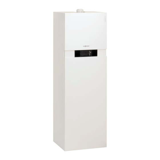
Viessmann Vitodens 242-F Installation And Service Instructions Manual
Gas/solar condensing storage combi boiler
Hide thumbs
Also See for Vitodens 242-F:
- Installation and service instructions manual (200 pages) ,
- Technical manual (112 pages) ,
- Installation and service instructions for contractors (144 pages)
Table of Contents
Advertisement
Quick Links
Advertisement
Table of Contents

Related Manuals for Viessmann Vitodens 242-F


Summary of Contents for Viessmann Vitodens 242-F
- Page 1 VIESMANN Installation and service instructions for contractors Vitodens 242-F Type B2UA, 3.2 to 26 kW Gas/solar condensing storage combi boiler Gas Council No. 41-819-18; 41-819-19 Natural gas and LPG versions For applicability, see the last page VITODENS 242-F Please keep safe.
- Page 2 ■ installer or a qualified person authorised by the For replacements, use only original spare parts installer. supplied or approved by Viessmann. Regulations to be observed Safety instructions for operating the system National installation regulations If you smell gas ■...
- Page 3 Safety instructions Safety instructions (cont.) What to do if water escapes from the appliance Danger When water escapes from the appliance there is a risk of electrocution. Switch off the heating system at the external iso- lator (e.g. fuse box, domestic power distribu- tion).
-
Page 4: Table Of Contents
Disposal of packaging ................Symbols ....................Intended use ..................Maintenance and cleaning ..............2. Preparing for installation Product information ................Vitodens 242-F, type B2UA ..............■ Installation preparations ................. Handling ..................... ■ Dividing the boiler into sections ............10 ■... - Page 5 Index Index 7. Diagnosis and service Service menu ..................89 scans Calling up the service menu ............... 89 ■ Exiting the service menu ..............89 ■ Diagnosis ....................89 Calling up operating data ..............89 ■ Brief scan .................... 90 ■...
-
Page 6: Index Index
Index Index (cont.) Loading cylinder assembly ..............138 Heat cell assembly .................140 MatriX cylinder burner assembly ............142 Control unit assembly ................144 Miscellaneous ..................146 12. Commissioning/service ........................148 reports 13. Specification ........................149 14. Certificates Declaration of conformity ............... 150 Manufacturer's certificate according to the 1st BImSchV [Germany] .. -
Page 7: Information Disposal Of Packaging
Please dispose of packaging waste in line with statu- DE: Use the disposal system organised by tory regulations. Viessmann. AT: Use the ARA statutory disposal system (Altstoff Recycling Austria AG, licence number 5766). CH: Packaging waste is disposed of by the HVAC contractor. -
Page 8: Maintenance And Cleaning
Information Intended use (cont.) Commercial or industrial usage for a purpose other Incorrect usage or operation of the appliance (e.g. the than heating the building or DHW shall be deemed appliance being opened by the system user) is prohibi- inappropriate. ted and will result in an exclusion of liability. -
Page 9: Preparing For Installation Product Information
Product information Vitodens 242-F, type B2UA Preset for operation with natural gas E and The Vitodens 242-F may only be delivered to countries natural gas LL. listed on the type plate. For deliveries to other coun- For conversion to LPG P (without conversion kit), see tries, approved contractors must arrange individual page 44. -
Page 10: Dividing The Boiler Into Sections
Preparing for installation Installation preparations (cont.) Dividing the boiler into sections 4. 2x Fig. 1... - Page 11 Preparing for installation Installation preparations (cont.) Fig. 2...
- Page 12 Preparing for installation Installation preparations (cont.) Fig. 3...
- Page 13 Preparing for installation Installation preparations (cont.) Fig. 4...
- Page 14 Preparing for installation Installation preparations (cont.) Fig. 5...
- Page 15 Preparing for installation Installation preparations (cont.) Fig. 6...
- Page 16 Preparing for installation Installation preparations (cont.) Fig. 7...
-
Page 17: Siting
Preparing for installation Installation preparations (cont.) Fig. 8 Siting Required room height: at least 2100 mm Preparing for boiler installation A connection set, available as an accessory, must be Please note used to make the connections on the gas and water Avoid appliance damage. - Page 18 Preparing for installation Installation preparations (cont.) The following overview shows sample connection sets for installation on finished walls, with connection to the top or side. Fig. 9 Solar return R ¾ Heating flow R ¾ DHW R ½ Gas connection R ½...
- Page 19 Preparing for installation Installation preparations (cont.) 1. Prepare the heating water connections. Thoroughly flush the heating system. Note Should an additional expansion vessel be required on site, connect this vessel in the heating return. 2. Prepare the connections on the DHW side. Install the safety assembly (accessory or on-site provi- sion) in the cold water line in accordance with DIN 1988 and EN 806 (see page 20).
- Page 20 Preparing for installation Installation preparations (cont.) Safety assembly to DIN 1988 and EN 806 on the cold water connection GH D D H L D N K Fig. 12 Safety assembly (accessory for connection sets for Drain unfinished walls) Cold water Safety valve Drinking water filter Visible discharge pipe outlet point...
-
Page 21: Installation Sequence Installing The Boiler
Installation sequence Installing the boiler Removing the front panels Fig. 13... -
Page 22: Siting And Levelling The Boiler
Installation sequence Installing the boiler (cont.) Siting and levelling the boiler SW17 Fig. 14... -
Page 23: Connections On The Heating Water And Dhw Side
Installation sequence Installing the boiler (cont.) Connections on the heating water and DHW side Fig. 15 Shown with connection sets for finished walls (accessories) Heating flow R Cold water R ¾ ½ DHW R Heating return R ½ ¾ DHW circulation R (separate accessory) ½... -
Page 24: Connections On The Solar Side
Installation sequence Installing the boiler (cont.) Connections on the solar side Fig. 16 Shown with connection sets for finished walls (accessories) Solar return, R or Ø 22 mm smooth pipe ¾ Solar flow, R or Ø 22 mm smooth pipe ¾... -
Page 25: Condensate Connection
■ Applicable regulations on installing and commission- tion may only be used in conjunction with the ing flue systems have been followed. Viessmann flue system made by Skoberne. During installation and positioning of the flue system, Danger ■ observe Part L and BS 5440 building regulations [GB Leaking or blocked flue systems or an insuffi- only]. -
Page 26: Gas Connection
Installation sequence Installing the boiler (cont.) Gas connection Fig. 18 Shown with connection sets for finished walls (accessories) Gas connection R ½ Information on operation with LPG 3. Purge the gas line. When installing the boiler in rooms below ground level we recommend fitting an external safety solenoid For conversion to a different gas type, see page 44 valve. -
Page 27: Opening The Control Unit Enclosure
Installation sequence Opening the control unit enclosure Fig. 19 Electrical connections Please note Electronic assemblies can be damaged by elec- trostatic discharge. Before beginning work, touch earthed objects, such as heating or water pipes, to discharge static loads. - Page 28 Installation sequence Electrical connections (cont.) 230V~ 230V~ 3 2 1 Fig. 20 Radio clock receiver Jumper Connections to 230 V~ plugs Information on connecting accessories Power supply When connecting accessories observe the sep- fÖ Power supply for accessories arate installation instructions provided with ■...
-
Page 29: Outside Temperature Sensor
Installation sequence Electrical connections (cont.) Outside temperature sensor For fitting the wireless outside temperature sensor Not immediately below balconies or gutters ■ (wireless accessory): ■ Never render over Wireless base station installation and service Outside temperature sensor connection instructions 2-core lead, length max. 35 m with a cross-section of Fitting location for outside temperature sensor 1.5 mm ■... -
Page 30: External Demand Via 0 - 10 V Input
Installation sequence Electrical connections (cont.) Plug EA1 extension Floating contact Floating contact (when connected, remove jumper EA1 extension between L and 1) Codes Codes "4b:1" in group "General"/1 Set "3A" (DE1), "3b" (DE2) or "3C" (DE3) to 2 in ■ ■... -
Page 31: Power Supply For Accessories At Plug Lh (230 V~)
Installation sequence Electrical connections (cont.) Please note Live contacts lead to short circuits or phase fail- ure. The external connection must be floating and meet the requirements of protection class II. Plug EA1 extension Floating contact Floating contact (when connected, remove jumper EA1 extension between L and 1) Codes... -
Page 32: Power Supply Fö
Installation sequence Electrical connections (cont.) Power supply to all accessories via heat source control unit Fig. 23 Some accessories with direct power supply Fig. 24 Heat source control unit Mains input fÖ Extension kit for heating circuit with mixer M2 A Power outlet fÖ... -
Page 33: Routing The Connecting Cables And Leads
Installation sequence Electrical connections (cont.) Routing the connecting cables and leads Please note Connecting cables/leads will be damaged if they touch hot components. When routing and securing cables/leads on site, ensure that the maximum permissible tempera- ture for these is not exceeded. Fig. -
Page 34: Closing The Control Unit Enclosure
Installation sequence Closing the control unit enclosure Fig. 26 Insert the programming unit (packed separately) into the control unit support. Note The programming unit can also be inserted into a wall mounting base (accessories) near the boiler. Wall mounting base installation instructions... -
Page 35: Fitting The Front Panels
Installation sequence Fitting the front panels Fig. 27... -
Page 36: Commissioning, Inspec-Steps - Commissioning, Inspection And Maintenance
Commissioning, inspection, maintenance Steps - commissioning, inspection and maintenance Commissioning steps Inspection steps Maintenance steps Page • • 1. Removing the front panels....................38 • 2. Checking the power supply • 3. Filling the heating system....................38 • 4. Filling the cylinder on the DHW side................39 •... - Page 37 Commissioning, inspection, maintenance Steps - commissioning, inspection and… (cont.) Commissioning steps Inspection steps Maintenance steps Page • • • 40. Checking the flue system for unrestricted flow and tightness • • • 41. Checking the external LPG safety valve (if installed) •...
-
Page 38: Removing The Front Panels
Commissioning, inspection, maintenance Removing the front panels See page 21. Checking the power supply Filling the heating system Fill water Please note Unsuitable fill water increases the level of deposits and corrosion and may lead to appli- ance damage. ■ Flush the heating system thoroughly before filling. -
Page 39: Filling The Cylinder On The Dhw Side
Commissioning, inspection, maintenance Filling the heating system (cont.) 4. Fill the heating system via boiler drain & fill valve 5. If the control unit was already on before filling in the heating return (depending on the connec- began: tion set either on the side or above the boiler). Switch the control unit ON and activate the fill pro- ■... -
Page 40: Setting The Time And Date
Commissioning, inspection, maintenance Changing the language (cont.) Sprache Deutsch ê ç Bulgarski ê Cesky ê Dansk ê Wählen mit Fig. 30 Setting the time and date The time and date need to be reset during commis- 3. "Time / Date" sioning or after a prolonged time out of use (approx. -
Page 41: Venting The Boiler
Commissioning, inspection, maintenance Venting the boiler 1. Close the shut-off valves on the heating water side. 2. Remove cover panel 3. Push the drain hose onto air vent valve and con- nect to a drain. 4. Open air vent valve and fill valve in the heat- ing return and vent (flush) using mains pressure... -
Page 42: Filling The Siphon With Water
Commissioning, inspection, maintenance Venting the heating system (cont.) 4. Check the system pressure. 5. Open the gas shut-off valve. Activating the venting function Service menu 1. Press OK and simultaneously for approx. 4 s. å 2. "Service functions" 3. "Venting" Venting function is enabled. -
Page 43: Filling The Solar Circuit
Commissioning, inspection, maintenance Filling the solar circuit Solar thermal system installation and service 1. Thoroughly flush the on-site pipework. instructions 2. Fill solar circuit with "Tyfocor LS" via fill valve ■ Minimum system pressure: 1.7 bar (0.17 MPa) Permissible operating pressure: 6 bar (0.6 MPa) ■... -
Page 44: Gas Type Conversion (Only For Operation With Lpg)
Commissioning, inspection, maintenance Checking the gas type (cont.) 1. Determine the gas type and Wobbe index by asking 3. Record the gas type in the report on page 148. your local gas supply utility or LPG supplier. 2. For operation with LPG, convert the burner (see page 44). - Page 45 Commissioning, inspection, maintenance Checking the static pressure and supply pressure (cont.) 2. Loosen the screw inside test connector "PE" 7. Record the actual value in the report on page 148. the gas train but do not remove it; then connect the Implement measures as indicated in the table pressure gauge.
-
Page 46: Function Sequence And Possible Faults
Commissioning, inspection, maintenance Function sequence and possible faults Display Measure Control unit issues a heat Increase set value and en- demand sure heat is drawn off Fan starts After approx. 51 s fault F9 Check the fan, fan connect- ing cables, power at the fan and fan control Ignition Fault EE... -
Page 47: Setting The Max. Heating Output
Commissioning, inspection, maintenance Setting the max. heating output The maximum output for heating operation can be 3. "Max. output" limited. The limit is set via the modulation range. The 4. "Change?" Select "Yes". max. adjustable output is limited upwards by the boiler A value is shown on the display (e.g. -
Page 48: Removing The Burner
Commissioning, inspection, maintenance Removing the burner Fig. 38 1. Switch OFF the power supply and the ON/OFF 4. Undo gas supply pipe fitting switch at the control unit. 5. Undo four screws and remove the burner. 2. Close the gas shut-off valve and safeguard against reopening. -
Page 49: Checking The Burner Gasket And Burner Gauze Assembly
Commissioning, inspection, maintenance Checking the burner gasket and burner gauze assembly Check burner gasket and burner gauze assembly for possible damage and replace if required. Fig. 39 1. Remove electrodes 5. Fit thermal insulation ring 2. Undo 2 retaining clips on thermal insulation ring 6. -
Page 50: Checking And Adjusting The Ignition And Ionisation Electrodes
Commissioning, inspection, maintenance Checking and adjusting the ignition and ionisation electrodes ±1 Fig. 40 Ignition electrodes Ionisation electrode 1. Check the electrodes for wear and contamination. 3. Check the electrode gaps. If the gaps are not as specified or the electrodes are damaged, replace 2. -
Page 51: Checking The Condensate Drain And Cleaning The Siphon
Commissioning, inspection, maintenance Checking the condensate drain and cleaning the siphon Flue gas cascade: Clean the trap in the flue gas header as well. Fig. 42 1. Check at the siphon that the condensate can drain 6. Clean the siphon. freely. -
Page 52: Installing The Burner
Commissioning, inspection, maintenance Installing the burner Fig. 43 1. Insert the burner and tighten screws crosswise. 4. Connect the electrical cables/leads: Torque: 8.5 Nm ■ Fan motor Ionisation electrode ■ 2. Fit gas supply pipe with a new gasket. ■ Gas train Torque: 30 Nm ■... -
Page 53: Checking The Anode Connection
Commissioning, inspection, maintenance Checking the anode connection Check that the earth cable is connected to the magne- sium anode. Fig. 44 Magnesium anode Earth cable Testing the anode earth current with an anode tester Note We recommend checking the magnesium anode func- tion annually. -
Page 54: Draining The Boiler On The Dhw Side
Commissioning, inspection, maintenance Testing the anode earth current with an anode… (cont.) 3. Connect tester (up to 5 mA) in series between tab and earth cable ■ If the current measures 0.3 mA the anode is > If the current measures < 0.3 mA or if there is no ■... -
Page 55: Cleaning The Loading Cylinder
Commissioning, inspection, maintenance Cleaning the loading cylinder Note According to EN 806, a visual inspection and (if neces- sary) cleaning must be carried out no later than two years after commissioning, and as required thereafter. Fig. 47 1. Drain the loading cylinder. 5. -
Page 56: Re-Assembling And Filling The Loading Cylinder
Commissioning, inspection, maintenance Re-assembling and filling the loading cylinder Fig. 48 1. Reconnect the loading cylinder to the pipework. 4. Push the earth cable onto tab 2. Insert new gasket at flange cover 5. Fit cover 3. Fit flange cover and tighten the 8 screws with a 6. -
Page 57: Checking The Pre-Charge Pressure And The Dhw Expansion Vessel (If Installed)
Commissioning, inspection, maintenance Checking the diaphragm expansion vessel and… (cont.) Note Check whether the installed diaphragm expansion ves- The diaphragm expansion vessel can lose charge sel is adequate for the system water volume. pressure over time in use. When the boiler heats up, the pressure gauge indicator may rise to 2 or 3 bar (0.2 or 0.3 MPa). -
Page 58: Checking All Gas Equipment For Tightness At Operating Pressure
Commissioning, inspection, maintenance Checking all gas equipment for tightness at operating pressure Danger Note Escaping gas leads to a risk of explosion. Only use suitable and approved leak detection agents Check all gas equipment for tightness. (EN 14291) and devices for the tightness test. Leak detection agents with unsuitable constituents (e.g. -
Page 59: Checking The External Lpg Safety Valve (If Installed)
Set the codes according to the accessories fitted: For individual coding steps, see page 68. Accessories installation and service instruc- tions System version 1 One heating circuit without mixer A1 Fig. 52 Vitodens 242-F Solar collectors Outside temperature sensor Collector temperature sensor Heating circuit without mixer A1... - Page 60 — — System version 2 One heating circuit with mixer M2 and low loss header Fig. 53 Vitodens 242-F Heating circuit pump M2 Outside temperature sensor Extension kit for one heating circuit with mixer M2 Heating circuit with mixer M2...
- Page 61 Matching the control unit to the heating system (cont.) System version 3 One heating circuit without mixer A1 and one heating circuit with mixer M2 Fig. 54 Vitodens 242-F Flow temperature sensor M2 Outside temperature sensor Heating circuit pump M2 Heating circuit without mixer A1...
- Page 62 Matching the control unit to the heating system (cont.) System version 4 One heating circuit without mixer A1, one heating circuit with mixer M2 and system separation Fig. 55 Vitodens 242-F Flow temperature sensor M2 Outside temperature sensor Heating circuit pump M2 Heating circuit without mixer A1...
- Page 63 One heating circuit without mixer A1, one heating circuit with mixer M2 (with extension kit), one heating circuit with mixer M3 (with extension kit) and low loss header (with/without DHW heating) Fig. 56 Vitodens 242-F Temperature limiter to restrict the maximum tem- Outside temperature sensor...
-
Page 64: Adjusting The Heating Curves
Commissioning, inspection, maintenance Adjusting the heating curves The heating curves illustrate the relationship between Note the outside temperature and the boiler water or flow If the heating system includes heating circuits with mix- temperature. ers, then the flow temperature of the heating circuit To put it simply, the lower the outside temperature, the without mixer is higher by a selected differential (8 K in higher the boiler water or flow temperature. -
Page 65: Connecting The Control Unit To The Lon
Commissioning, inspection, maintenance Adjusting the heating curves (cont.) Reduced set room temperature Fig. 59 Example 2: Adjustment of the reduced set Outside temperature in °C room temperature from 5 °C to 14 °C Fig. 60 Boiler water temperature or flow temperature in °C Outside temperature in °C Changing the slope Set room temperature in °C... -
Page 66: Scanning And Resetting The "Service" Display
Control unit receives outside — temperature. temperature. temperature. Set code "97:2". Set code "97:1". Set code "97:1". Viessmann system number. Viessmann system number. Viessmann system number. — Code "98:1" Code "98:1" Code "98:1" LON subscriber fault monitor- LON subscriber fault moni- LON subscriber fault moni- —... -
Page 67: Instructing The System User
Commissioning, inspection, maintenance Instructing the system user The system installer should hand the operating instruc- tions to the system user and instruct the user in oper- ating the system. This includes all components installed as accessories, e.g. remote control units. In addition, the system instal- ler must make the user aware of the required mainte- nance work. -
Page 68: General
Code 1 (cont.) On weather-compensated control units, codes are ■ displayed as plain text. ■ Codes that are not assigned, due to the heating sys- tem equipment level or the setting of other codes, are not displayed. Heating systems with one heating circuit without ■... -
Page 69: Boiler
Code 1 "General" (cont.) Value, ad- Description dress 00: ... One heating circuit with mixer M2 (heating circuit 2) One heating circuit with mixer M3 (heating circuit 3) One heating circuit without mixer A1 (heating circuit 1) Two heating circuits with mixer M2 (heating circuit 2) and M3 (heating circuit 3) (code is set automatically) Coding in the delivered condition Possible change... -
Page 70: Coding
Code 1 "Boiler" (cont.) Coding Coding in the delivered condition Possible change Burner service in 100 hours 21:0 No service interval set (in hours 21:1 The number of hours run before the run) burner should be serviced is adjust- 21:100 able from 100 to 10 000 h. -
Page 71: Coding
Code 1 "Solar" (cont.) Coding Coding in the delivered condition Possible change Speed control solar circuit pump 02:1 Solar circuit pump (multi stage) is 02:0 Solar circuit pump (multi stage), not speed-controlled with wave packet speed-controlled control 02:2 Do not adjust Maximum cylinder temperature 08:60 Set DHW temperature (maximum... - Page 72 Code 1 "Heating circuit ..." (cont.) Coding in the delivered condition Possible change Extended economy function adjusted outside temperature A6:36 Extended economy mode not ac- A6:5 Extended economy mode enabled; tive i.e. at a variably adjustable value be- A6:35 tween 5 and 35 °C, plus 1 °C, the burner and heating circuit pump stop and the mixer closes.
- Page 73 Code 1 "Heating circuit ..." (cont.) Parameter address With heating circuit pump logic function: b5:... Heating circuit pump "OFF" Heating circuit pump "ON" + 1 K < RT > actual actual < RT > – actual actual < RT > –...
- Page 74 Code 1 "Heating circuit ..." (cont.) Coding in the delivered condition Possible change Screed drying F1:0 Screed drying not active. F1:1 Only for heating circuit with mixer: Screed drying adjustable, with F1:6 choice of 6 temperature/time profiles (see page 119) F1:15 Constant flow temperature 20 °C Party mode time limit...
-
Page 75: General
Code 2 (cont.) In coding level 2 all codes are accessible. ■ ■ Codes that are not assigned, due to the heating sys- tem equipment level or the setting of other codes, are not displayed. ■ Below, the heating circuit without mixer is designated "Heating circuit 1"... - Page 76 Code 2 "General" (cont.) Value, ad- Description dress 00: ... One heating circuit with mixer M2 (heating circuit 2) One heating circuit with mixer M3 (heating circuit 3) One heating circuit without mixer A1 (heating circuit 1) Two heating circuits with mixer M2 (heating circuit 2) and M3 (heating circuit 3) (code is set automatically) Coding in the delivered condition Possible change...
- Page 77 Code 2 "General" (cont.) Coding in the delivered condition Possible change Set value setting: Coding address "9b" in this group. Internal circulation pump function: Coding address "3F" in this group. 3b:3 Function of DE2 input: External blocking. Internal circulation pump function: Coding address "3E"...
- Page 78 Code 2 "General" (cont.) Coding in the delivered condition Possible change 51:0 The internal circulation pump al- 51:1 System with low loss header: ways starts when there is a heat The internal circulation pump only demand. starts upon heat demand if the burn- er is running.
- Page 79 Vitotronic 200-H 98:1 With LON communication module: 98:1 System number adjustable from 1 to Viessmann system number (in conjunction with monitoring of sev- 98:5 eral systems via Vitocom 300) 99:0 Do not adjust...
-
Page 80: Boiler
Code 2 "General" (cont.) Coding in the delivered condition Possible change If there is no response from a sub- scriber for 20 min, the values specified in the control unit are used. Only then will a fault mes- sage be issued. (Only for weather- compensated control units.) 9F:8 Only for heating circuit with mixer:... -
Page 81: Dhw
Code 2 "Boiler" (cont.) Coding in the delivered condition Possible change 31:... Set speed of the internal circula- 31:0 Set speed adjustable from 0 to tion pump when operated as boiler 100 % circuit pump in %, specified by the 31:100 boiler coding card 38:0... -
Page 82: Solar
Code 2 "DHW" (cont.) Coding in the delivered condition Possible change 72:2 "ON" during DHW heating to set val- ue 2 73:0 DHW circulation pump: "ON" ac- 73:1 During time program cording to time program "ON" from once per hour for 5 min to 73:6 "ON"... -
Page 83: Heating Circuit
0E:1 Solar yield calculated in connec- 0E:2 Solar yield calculated in connection tion to Viessmann heat transfer to water as heat transfer medium. medium. Never adjust 0E:0 No heat statement... - Page 84 Code 2 "Heating circuit ..." (cont.) Please note With settings below 1 °C there is a risk that pipes outside the thermal envelope of the building could freeze Standby mode in particular must be taken into consideration, e.g. during holidays. Parameter Heating circuit pump address A3:...
- Page 85 Code 2 "Heating circuit ..." (cont.) Coding in the delivered condition Possible change A6:36 Extended economy mode not ac- A6:5 Extended economy mode enabled; tive i.e. at a variably adjustable value be- A6:35 tween 5 and 35 °C, plus 1 °C, the burner and heating circuit pump stop and the mixer closes.
- Page 86 Code 2 "Heating circuit ..." (cont.) Parameter address With heating circuit pump logic function: b5:... Heating circuit pump "OFF" Heating circuit pump "ON" + 3 K < RT + 2 K > actual actual + 2 K < RT + 1 K >...
- Page 87 Code 2 "Heating circuit ..." (cont.) Coding in the delivered condition Possible change No display correction for the actual E2:49 Display correction 0.1 K – room temperature (only for weath- E2:51 Display correction +0.1 K er-compensated control units) E2:99 Display correction +4.9 K E5:0 Do not adjust E6:...
- Page 88 Code 2 "Heating circuit ..." (cont.) Coding in the delivered condition Possible change F8:–5 Temperature limit for terminating F8:+10 Temperature limit adjustable from reduced mode 5 °C, see example +10 to 60 °C – – on page 121. F8:–60 Observe setting for coding address F8:–61 Function not active "A3".
-
Page 89: Diagnosis And Service Service Menu
Diagnosis and service scans Service menu Calling up the service menu 1. Press OK and simultaneously for approx. 4 s. å 2. Select required menu. See following diagram. Exiting the service menu 1. Select "Terminate service?". Note 2. Select "Yes". The system exits the service level automatically after 3. -
Page 90: Brief Scan
Diagnosis and service scans Diagnosis (cont.) 4. Select required value (e.g. "Burner starts") or "All details". Brief scan In the brief scan, you can call up temperatures, soft- ware versions and connected components, for exam- ple. 1. Press OK and simultaneously for approx. -
Page 91: Checking Outputs (Actuator Test)
Diagnosis and service scans Diagnosis (cont.) Row (brief Field scan) Heating circuit A1 (without Heating circuit M2 (with Heating circuit M3 (with mix- mixer) mixer) Remote con- Software ver- Remote con- Software ver- Remote con- Software ver- trol sion, remote trol sion, remote trol... - Page 92 Diagnosis and service scans Checking outputs (actuator test) (cont.) Display Explanation Mixer HC3 Open "Mixer open" output enabled (extension to heating circuit with mixer) Mixer HC3 Close "Mixer close" output enabled (extension to heating circuit with mixer) Outp. int. exten. H1 Output at internal extension enabled AM1 output 1 Output A1 at extension AM1 enabled...
-
Page 93: Troubleshooting Fault Display
Troubleshooting Fault display Calling up acknowledged faults In the event of a fault, red fault indicator flashes. " " flashes on the display and "Fault" is shown. Select "Fault" in the standard menu. The current faults will be displayed in a list. Calling up fault codes from the fault memory (fault history) The 10 most recent faults (including resolved ones) - Page 94 Troubleshooting Fault codes (cont.) Fault code dis- System characteristics Cause Measures played Regulates without flow tem- Short circuit, system flow Check low loss header sensor (see perature sensor (low loss temperature sensor page 103) header) Regulates without flow tem- Lead break, system flow Check low loss header sensor (see perature sensor (low loss temperature sensor...
- Page 95 Troubleshooting Fault codes (cont.) Fault code dis- System characteristics Cause Measures played Control mode No flow rate in solar circuit Check solar circuit. or flow rate too low, or Acknowledge fault message (see temperature limiter has separate installation and service triggered.
- Page 96 Troubleshooting Fault codes (cont.) Fault code dis- System characteristics Cause Measures played Control mode without remote Communication error, Check connections, cable and cod- control Vitotrol remote control, ing address "A0" in group "Heat- heating circuit 2 (with mix- ing circuit", and check remote control configuration (see page 123).
- Page 97 Troubleshooting Fault codes (cont.) Fault code dis- System characteristics Cause Measures played Control mode without room Short circuit, room tem- Check room temperature sensor, influence perature sensor, heating heating circuit 2 circuit 2 (with mixer) Control mode without room Short circuit, room tem- Check room temperature sensor, influence perature sensor, heating...
- Page 98 Troubleshooting Fault codes (cont.) Fault code dis- System characteristics Cause Measures played Burner in a fault state Ionisation current outside Check flue system; remedy flue permissible range during gas recirculation if required. calibration (excessive de- In open flue operation, prevent viation from previous lev- high incidence of dust in the com- bustion air.
- Page 99 Troubleshooting Fault codes (cont.) Fault code dis- System characteristics Cause Measures played Burner in a fault state Temperature limiter has Check heating system fill level. triggered. Check circulation pump. Vent the system. Check temperature limiter and connecting cables. Press reset button R. Burner in a fault state Flame signal is already Check ionisation electrode and...
-
Page 100: Maintenance
Troubleshooting Maintenance Please note Residual water will escape when the boiler or one of the following components is fitted or removed: ■ Water-filled pipework Circulation pumps ■ Plate heat exchanger ■ Components fitted in the heating water or ■ DHW circuit Water ingress can result in damage to other components. -
Page 101: Draining The Boiler On The Heating Water Side
Troubleshooting Maintenance (cont.) Draining the boiler on the heating water side Fig. 65 1. Close the shut-off valves on the heating water side. 3. Open drain valve and drain the boiler as much as required. 2. Route hose at drain valve into a suitable con- tainer or drain outlet. - Page 102 Troubleshooting Maintenance (cont.) 1. Pull plug "X3" from the control unit. 2. Test the resistance of the outside temperature sen- sor across terminals "X3.1" and "X3.2" on the dis- connected plug and compare it with the curve. 3. Where actual values deviate severely from the curve values, disconnect the wires at the sensor and repeat the test on the sensor itself.
-
Page 103: Checking The Boiler Temperature Sensor, Cylinder Temperature Sen- Sor Or Flow Temperature Sensor For Low Loss Header
Troubleshooting Maintenance (cont.) Checking the boiler temperature sensor, cylinder temperature sensor or flow temperature sen- sor for low loss header Fig. 68 ■ Boiler water temperature sensor Pull out the leads at boiler water temperature sen- and check the resistance. Cylinder temperature sensor ■... -
Page 104: Checking The Collector Temperature Sensor Or Cylinder Temperature Sensor On The Solar Control Module
Troubleshooting Maintenance (cont.) 3. In the event of severe deviation replace the sensor. Danger The boiler water temperature sensor is directly immersed in the heating water (risk of scalding). Drain the boiler on the heating water side before replacing the sensor. Checking the collector temperature sensor or cylinder temperature sensor on the solar control module The solar control module is attached to the left side of... -
Page 105: Checking The Outlet Temperature Sensor
Troubleshooting Maintenance (cont.) Checking the outlet temperature sensor 10 30 50 70 90 110 Temperature in °C Fig. 73 Sensor type: NTC 10 k Ω 1. Pull leads from outlet temperature sensor 2. Check the sensor resistance and compare it to the curve. -
Page 106: Checking The Flue Gas Temperature Sensor
Troubleshooting Maintenance (cont.) Fig. 74 1. Shut off and drain the boiler on the heating water 5. Undo two screws and remove plate heat and DHW sides. exchanger with insulation through the front. 2. Release side fasteners and pivot control unit for- 6. -
Page 107: Checking The Temperature Limiter
Troubleshooting Maintenance (cont.) 10 30 50 70 90 110 Temperature in °C Fig. 76 Sensor type: NTC 10 k Ω 1. Pull out leads at flue gas temperature sensor 2. Check the sensor resistance and compare it to the curve. 3. - Page 108 Troubleshooting Maintenance (cont.) Fig. 77 1. Pull out the leads at temperature limiter 2. Check the continuity of the temperature limiter with a multimeter. 3. Remove faulty temperature limiter. 4. Coat the new temperature limiter with heat conduct- ing paste and install it. 5.
-
Page 109: Checking The Fuse/Mcb
Troubleshooting Maintenance (cont.) Checking the fuse/MCB Fig. 78 1. Switch off the power supply. 3. Remove cover 2. Release the side closures and pivot the control unit 4. Check fuse F1 (see connection and wiring dia- down. gram). Checking the solar control module fuse Fig. - Page 110 Troubleshooting Maintenance (cont.) Observe the rotational direction of the mixer motor dur- Heating circuit Rotary selector S1 ing its self-test. setting Then manually set the mixer back to "Open". Heating circuit with mixer M2 The flow temperature sensor must now capture a (heating circuit 2) higher temperature.
-
Page 111: Checking The Vitotronic 200-H (Accessories)
Troubleshooting Maintenance (cont.) Checking the Vitotronic 200-H (accessories) The Vitotronic 200-H is connected to the control unit via the LON cable. To test the connection, carry out a subscriber check at the boiler control unit (see page 66). -
Page 112: Function Description Control Unit
Function description Control unit Boiler temperature 48 °C Heating Solar energy Information Select with Fig. 82 Heating mode The control unit determines a set boiler water tempera- The electronic temperature limiter inside the burner ture subject to outside temperature or room tempera- control unit limits the boiler water temperature. -
Page 113: Dhw Heating Via Solar Collectors
Function description Control unit (cont.) DHW heating via solar collectors If the temperature differential measured between the The pump is stopped when the temperature falls below collector temperature sensor and the cylinder tempera- the stop temperature differential between the collector ture sensor of the solar control module is greater than temperature sensor and the cylinder temperature sen- the start temperature differential set in the control unit,... -
Page 114: Internal Extension H2
Function description Internal extensions (accessories) (cont.) Internal extension H2 Fig. 84 The internal extension is integrated into the control unit ■ Heating circuit pump for heating circuit without mixer enclosure. The following alternative functions can be (code "53:2") connected to relay output . -
Page 115: External Extensions (Accessories)
Function description External extensions (accessories) AM1 extension Fig. 85 Circulation pump A Power supply for additional accessories fÖ Circulation pump KM BUS Power supply fÖ Functions Select the output functions by means of the codes on the boiler control unit. One of the following circulation pumps can be connec- ted to each of the connections A1 and A2: ■... -
Page 116: Ea1 Extension
Function description External extensions (accessories) (cont.) Function assignment Function Code ("General" group) Output A1 Output A2 DHW circulation pump 33:0 34:0 (delivered condition) Heating circuit pump 33:1 (delivered condition) 34:1 sÖ Circulation pump for cylinder heating 33:2 34:2 EA1 extension Fig. - Page 117 Function description External extensions (accessories) (cont.) Central fault message/feed pump/DHW circula- tion pump (potential-free) Connect DHW circulation pumps with stand- ∼ alone functions directly to the 230 V supply. KM BUS Digital data inputs DE1 to DE3 Effect of the external demand function on the pumps The following functions can be connected alternatively: ■...
-
Page 118: Control Functions
Function description Control functions External operating program changeover The "External operating program changeover" function The function is selected via the following coding is implemented via the EA1 extension. There are 3 addresses in the "General" group: inputs available at the EA1 extension (DE1 to DE3). Heating program changeover Code Input DE1... -
Page 119: External Demand
Function description Control functions (cont.) External blocking and fault message input Code Input DE1 3A:4 Input DE2 3b:4 Input DE3 3C:4 The effect on the internal circulation pump is selected The effect on the relevant heating circuit pump is in coding address "3E" in the "General" group. selected in coding address "d6"... - Page 120 Function description Control functions (cont.) Note Various temperature profiles can be set via coding Temperature profile 6 ends after 21 days. address "F1" in the "Heating circuit" group. The function continues after power failure or after the Observe EN 1264. The report to be provided by the control unit has been switched off.
-
Page 121: Raising The Reduced Room Temperature
Function description Control functions (cont.) Temperature profile 5: Code "F1:5" Days Fig. 91 Temperature profile 6: Code "F1:6" Days Fig. 92 Ends after 21 days Temperature profile 7: Code "F1:15" Days Fig. 93 Raising the reduced room temperature During operation at reduced room temperature, the The outside temperature limits for the start and end of reduced set room temperature can be automatically temperature raising can be set in coding addresses... -
Page 122: Reducing The Heat-Up Time
Function description Control functions (cont.) Example using the settings in the delivered condition Outside temperature in °C Fig. 94 Heating curve for operation with standard room temperature Heating curve for operation with reduced room temperature Reducing the heat-up time During the transition from operation with reduced room The value and duration for the additional increase of temperature to operation with standard room tempera- the set boiler water or flow temperature is selected in... -
Page 123: Allocating Heating Circuits To The Remote Control
Function description Control functions (cont.) Example using the settings in the delivered condition Time Fig. 95 Start of operation with standard room temperature Set boiler water or flow temperature in accordance with the selected heating curve Set boiler water or flow temperature in accordance with coding address "FA": 50 °C + 20 % = 60 °C Duration of operation with raised set boiler water... -
Page 124: Electronic Combustion Control Unit
Function description Electronic combustion control unit The electronic combustion controller utilises the physi- To check the combustion quality, the CO content or cal correlation between the level of the ionisation cur- the O content of the flue gas is measured. The pre- rent and the air ratio . -
Page 125: Designs Internal Connection Diagram
Designs Internal connection diagram Fig. 96 Main PCB Stepper motor for diverter valve dÖ X... Electrical interfaces Thermal circuit breaker Boiler water temperature sensor § Ignition unit Outlet temperature sensor Fan motor a-Ö Ionisation electrode A Fan motor control a-Ö Flue gas temperature sensor Modulation coil a:Ö... -
Page 126: External Connection Diagram
Designs External connection diagram Fig. 97 Main PCB Flow temperature sensor, low loss header Power supply unit Cylinder temperature sensor (plug on cable har- Optolink ness) Burner control unit Internal circulation pump sÖ Programming unit Cylinder loading pump Coding card Gas solenoid valve Connection adaptor Power supply... -
Page 127: Connection Diagram, Solar Control Module
Designs Connection diagram, solar control module Fig. 98 Main PCB Cylinder temperature sensor PWM Speed control, solar circuit pump & Collector temperature sensor X... Electrical interfaces Solar circuit pump KM BUS from the control unit Power supply fÖ Power supply from the control unit KM BUS Terminal box, collector temperature sensor... -
Page 128: Parts Lists Ordering Parts
Parts lists Ordering parts The following information is required: ■ Serial no. (see type plate ■ Assembly (from the parts list) ■ Position number of the individual part within the assembly (from this parts list) -
Page 129: Overview Of Assemblies
Parts lists Overview of assemblies Fig. 99 Type plate Heat cell assembly with MatriX cylinder burner Casing assembly Control unit assembly Hydraulic assembly with hydraulic block Miscellaneous assembly Loading cylinder assembly... -
Page 130: Casing Assembly
Parts lists Casing assembly 0011 0008 0012 0007 0005 0005 0013 0013 0006 0005 0014 0002 0013 0014 0004 0013 0009 0001 0003 0013 Fig. 100... - Page 131 Parts lists Casing assembly (cont.) Pos. Part 0001 Side panel, right 0002 Front panel, top 0003 Adjustable foot 0004 Control unit support 0005 Profiled seal 0006 Cover panel with profiled seal 0007 Toggle fastener (4 pce) 0008 Side panel, left 0009 Front panel, bottom 0010...
-
Page 132: Hydraulic Assembly
Parts lists Hydraulic assembly 0046 0030 0050 0047 0002 0012 0037 0029 0008 0002 0005 0003 0036 0008 0009 0009 0047 0033 0043 0043 0033 0046 0006 0047 0008 0005 0020 0047 0005 0005 0026 0046 0001 0035 0026 0012 0006 0047 0047... - Page 133 Parts lists Hydraulic assembly (cont.) Pos. Part 0001 Hydraulic block 0002 Set of plug-in connector retainers (2 pce) 0003 Diaphragm grommet (5 pce) 0004 Diaphragm grommet (5 pce) 0005 Clip Ø 8 (5 pce) 0006 Clip Ø 10 (5 pce) 0007 Clip Ø...
- Page 134 Parts lists Hydraulic assembly (cont.) Pos. Part 0045 Cap G 3/4 SW 30 0046 Gasket A 10 x 15 x 1.5 (5 pce) 0047 O-ring 17.86 x 2.62 (5 pce) 0048 O-ring 14.3 x 2.4 (5 pce) 0049 Spring clip DN 25 (5 pce) 0050 Plug 0051...
- Page 135 Parts lists Hydraulic assembly...
-
Page 136: Cylinder Module Assembly
Parts lists Cylinder module assembly 0002 0020 0023 0024 0023 0026 0024 0003 0023 0013 0023 0024 0017 0024 0004 0017 0001 0002 0012 0004 0022 0024 0029 0028 0024 0024 0010 0024 0027 0024 0008 0018 0016 0002 0027 0021 0024 0019... - Page 137 Parts lists Cylinder module assembly (cont.) Pos. Part 0001 Loading cylinder 0002 Pipe clip Ø 18 0003 Sleeve G 1 0004 Pipe clip Ø 18 / 1.5 0005 Drip pan 0006 Hose 12 x 3 l = 1300 0007 Sensor well with clamp G 1/2 l = 150 0008 Non-return valve with body 1 (fem.) x 1 (male) 0009...
-
Page 138: Loading Cylinder Assembly
Parts lists Loading cylinder assembly 0009 0007 0005 0004 0008 0004 0007 0006 0003 0001 0002 0010 Fig. 103... - Page 139 Parts lists Loading cylinder assembly (cont.) Pos. Part 0001 Loading cylinder 0002 Sensor retainer 0003 Magnesium anode 0004 Gasket 0005 Flange with gasket 0006 Cover 0007 Gasket 23 x 30 x 2 (5 pce) 0008 Sleeve 0009 Flange insulation 0010 Cylinder temperature sensor NTC 10k Ω...
-
Page 140: Heat Cell Assembly
Parts lists Heat cell assembly 0008 0005 0006 0009 0007 0015 0007 0008 0023 0024 0004 0007 0023 0009 0002 0003 0023 0004 0023 0011 0009 0001 0023 0009 0003 0020 0012 0015 0014 0016 0013 0012 0015 0016 0021 0014 0018 0009... - Page 141 Parts lists Heat cell assembly (cont.) Pos. Part 0001 MatriX cylinder burner 0002 Heat exchanger 0003 Thermal insulation block 0004 Flue gasket 0005 Flue gas temperature sensor 0006 Boiler flue connection 0007 Plug for boiler flue connection 0008 Gasket DN 60 0009 Spring clip DN 25 (5 pce) 0010...
-
Page 142: Matrix Cylinder Burner Assembly
Parts lists MatriX cylinder burner assembly 0002 0001 0003 0018 0004 0010 0004 0018 0001 0004 0007 0012 0015 0013 0020 0005 0013 0018 0013 0012 0006 0014 0012 0011 0007 0019 0008 0017 0007 0019 0009 0016 Fig. 105... - Page 143 Parts lists MatriX cylinder burner assembly (cont.) Pos. Part 0001 Burner gasket (wearing part) 0002 Thermal insulation ring 0003 Cylinder, burner gauze assembly 0004 Gasket, burner gauze assembly 0005 Ignition electrode (wearing part) 0006 Ionisation electrode (wearing part) 0007 Gasket, burner door flange (wearing part) 0008 Radial fan 0009...
-
Page 144: Control Unit Assembly
Parts lists Control unit assembly 0013 0002 0009 0008 0005 0009 0015 0020 0001 0003 0015 0021 0014 0005 0004 0015 0017 0007 0018 0010 0011 0012 0019 0022 0023 0024 Fig. 106... - Page 145 Parts lists Control unit assembly (cont.) Pos. Part 0001 Control unit 0002 Control unit casing back panel 0003 Coding card 0004 Fuse 6.3 A (slow) (10 pce) 0005 Fuse holder 0007 Programming unit for weather-compensated mode 0008 LON module 0009 PCB adaptor 0010 Cable harness X8/X9/ionisation...
-
Page 146: Miscellaneous
Parts lists Miscellaneous 0002 0003 0004 0001 0005 0006 Fig. 107... - Page 147 Parts lists Miscellaneous (cont.) Pos. Part 0001 Special grease 0002 Touch-up spray paint, white 0003 Touch-up paint stick, white 0004 Installation and service instructions 0005 Operating instructions for constant temperature mode 0006 Operating instructions for weather-compensated mode...
-
Page 148: Commissioning/Service
Commissioning/service reports Commissioning/service reports Settings and test values Set value Commissioning Maintenance/ service Date Signature Static pressure mbar 57.5 ≤ 5.75 ≤ Supply pressure (flow pressure) for natural gas E mbar 17-25 1.70-2.5 for natural gas LL mbar 17-25 1.70-2.5 for LPG mbar 42.5-57.5... -
Page 149: Specification
Specification Specification Rated heating output range at T 50/30 °C 3.2 (4.8) - 13 3.2 (4.8) - 19 5.2 (8.8) - 26 at T 80/60 °C 2.9 (4.3) - 11.8 2.9 (4.3) - 17.2 4.7 (8.0) - 23.7 for DHW heating 2.9 (4.3) - 17.2 2.9 (4.3) -
Page 150: Certificates Declaration Of Conformity
Certificates Declaration of conformity We, Viessmann Werke GmbH & Co KG, D-35107 Allendorf, declare as sole responsible body that the product Vitodens 242-F, type B2UA, complies with the following standards: DIN 4753 EN 55 014 EN 483 EN 60 335-1... -
Page 151: Keyword Index
Keyword index Keyword index Function descriptions..........112 Acknowledging a fault display........93 Fuse/MCB..............109 Actuator test............... 91 Assembly..............128 Gas supply pressure..........45 Gas train ..............45 Boiler draining Gas type..............43 – DHW side..............54 Gas type conversion..........44 – Heating water side..........101 Boiler water temperature sensor...... - Page 152 Static pressure............45 Supply pressure............44 Applicability Serial No.: 7519083 7513244 7513245 Viessmann Werke GmbH & Co. KG Viessmann Limited D-35107 Allendorf Hortonwood 30, Telford Telephone: +49 6452 70-0 Shropshire, TF1 7YP, GB Fax: +49 6452 70-2780 Telephone: +44 1952 675000 www.viessmann.com...
Need help?
Do you have a question about the Vitodens 242-F and is the answer not in the manual?
Questions and answers