
Related Manuals for Alpha 8100


Summary of Contents for Alpha 8100
- Page 1 ALPHA 8100 HF LINEAR AMPLIFIER OPERATING MANUAL © 2006 Alpha Radio Products, Inc All rights reserved Specifications subject to change without notice ALPHA 8100 OPERATING MANUAL www.alpharadioproducts.com...
- Page 2 ALPHA 8100 OPERATING MANUAL www.alpharadioproducts.com...
-
Page 3: Table Of Contents
4.2.3 Power Cord Connections 21 4.2.4 Important Information About Operation from 90-130V AC 21 4.3 AC Primary Connections 22 4.4 Complete the Transformer Installation 25 4.4.1 RF Grounding 25 4.4.2 Replacing the Amplifier Cover 25 ALPHA 8100 OPERATING MANUAL www.alpharadioproducts.com... - Page 4 5.8 Display Board 31 5.9 Output Wattmeter Board 31 5.10 Center Partition Board 32 Operation & Maintenance 6.1 Before Operating Your Alpha 8100 33 6.1.1 Setting Input Drive 33 6.1.2 Dealing with Faults 33 6.1.3 High SWR Considerations 35 6.1.4 Operating at Less Than 1.5 kW Requires Retuning 35 6.1.5 Lightning Protection 36...
- Page 5 6.4.5 Idling Plate Current and Electronic Bias Control (Ebs) 44 6.4.6 RF and Mistuning Protection 44 6.5 Standard Maintenance Tasks 45 Troubleshooting Hints 7.1 Normal Troubleshooting 47 7.2 Troubleshooting Using the Serial Port 50 Glossary ALPHA 8100 OPERATING MANUAL www.alpharadioproducts.com...
- Page 6 ALPHA 8100 OPERATING MANUAL www.alpharadioproducts.com...
-
Page 7: Introduction
The Alpha 8100 is a self-contained manual tune HF linear power amplifier capable of continuous operation at 1500 W peak power output on SSB, keyed CW, SSTV, RTTY, digital modes or FM, with no time limit. -
Page 8: Amplifier Capabilities
1.4 Safety Information – Installation and Operation • Make sure the Alpha 8100 is located where there is good air circulation all around and on top of the cabinet. The unit may become hot during operation. • The Alpha 8100 weighs approximately 68 pounds when the transformer is installed. Use proper lifting techniques and two people when moving the amplifier. -
Page 9: Owner Assistance
• The Alpha 8100 is designed to meet international safety standards and FCC regulations. However, one should always remember that the equipment works with high voltages that can be LETHAL! This operating manual holds information, cautions and warnings that must be followed to ensure safe installation and operation. - Page 10 • FAQs • You can e-mail us for customer support at service@alpharadioproducts.com or you can send your request by fax to 303.473.9660. ALPHA 8100 OPERATING MANUAL www.alpharadioproducts.com...
-
Page 11: Quick Start Information
2.2 Station Engineering Considerations - Checklist Make sure you have properly addressed the following concerns (Section 2.3 below) before installation of your Alpha 8100 amplifier. If you are unsure of any of these items, please read the noted sections carefully. -
Page 12: Unpacking
__ Amplifier Grounded Properly? (Section 4.4.1) __ Amplifier Cover Replaced and Secured? (Section 4.4.2) 2.5 Operation __ All Exciter Interconnections Set? (Section 6.2) __ Exciter Drive Correctly Set? (Section 6.1.1) __ Amplifier Tuned to Antenna System? (Section 6.3.6) ALPHA 8100 OPERATING MANUAL www.alpharadioproducts.com... -
Page 13: Station Engineering Considerations
Ask the contractor to measure the voltage and record it, so you can set the line voltage tap on the 8100 appropriately. If possible, have the contractor measure the line voltage with a 10 amp current draw, and use this value for setting the transformer tap. -
Page 14: Antennas
Try to minimize the possibility of dust or other contamination getting drawn into or falling on the amplifier. It is also advisable to periodically (at least annually) clean the dust out of your amplifier for continued flawless operation. Alpha Radio Products recommends the use of compressed air for dust removal. -
Page 15: Coax And Connectors
The FCC requires users to check their installations for compliance with published values for allowable exposure to RF fields. This information is available in ARRL publications, FCC printed rules, and on the web. Alpha Radio Products strongly recommends that this be done for any installation, both fixed and at an expedition or contest site. - Page 16 ALPHA 8100 OPERATING MANUAL www.alpharadioproducts.com...
-
Page 17: Unpacking & Preparation
It is recommended that the power transformer be installed when the amp is at or near the place it is to be used. The chassis of the 8100 is designed for the mechanical loads it experiences when the amplifier is on a flat surface with the tilt-bail up or down. If the amplifier is tilted too far, such that the transformer is cantilevered or “hanging out”... -
Page 18: Install The Power Transformer
Failure to ensure proper cooling airflow may result in tube damage or destruction, which is not covered under warranty. ALPHA 8100 OPERATING MANUAL www.alpharadioproducts.com... -
Page 19: Transformer Installation
(1/4 / 20, ½” hex bolts) with ¼” washers through the four clearance holes in the chas- sis and into the nuts in the transformer base. Once the transformer is secure you may carefully rotate the amplfier back to its standard orientation. ALPHA 8100 OPERATING MANUAL www.alpharadioproducts.com... -
Page 20: Connecting The Transformer Power Plugs
Gently Gently but firmly but firmly but firmly press the press the press the connectors connectors connectors together together together till they till they till they are fully are fully are fully mated. mated. mated. ALPHA 8100 OPERATING MANUAL www.alpharadioproducts.com... -
Page 21: Power Cord Connections
ALWAYS use grounding type AC connectors which conform to local codes and ensure that the green wire in the Alpha 8100 power cable is wired only to the AC mains safety ground (or to neutral, as may be necessary with a 240V circuit configured 120V-N-120V without a separate ground, commonly found in the US). -
Page 22: Ac Primary Connections
90-110 volts, then power outputs above 1,000 watts should not be expected from the amplifier. Tune (adjust) the amplifier for no more than 1,000 watts output, and simultaneously for maximum efficiency. ALPHA 8100 OPERATING MANUAL www.alpharadioproducts.com... - Page 23 Be sure that the AC cord is not coiled too tightly or placed where normal air flow is restricted because the cord could overheat. If other equipment is drawing current from the same circuit as the Alpha 8100, then the considerations in section 4.2.3 should be taken into account.
- Page 24 220 and 240 Volts. The acceptable line voltage for each tap is the center voltage plus or minus 10 Volts. One of these taps is suitable for any of the “nominal” line voltages encountered worldwide. ALPHA 8100 OPERATING MANUAL www.alpharadioproducts.com...
-
Page 25: Complete The Transformer Installation
Do not attempt to operate the amplifier with the cover removed or only placed back on the unit without the attachment screws. This WILL cause damage to the Alpha 8100 and may also lead to injury or death to the operator. 4.4.3 Blower Preparation The cooling fan is secured to the rear panel for shipping. -
Page 26: T/R Control Cable
Shielded wire should be used for the T/R control cable. The Alpha 8100 end must be fitted with a common phono (RCA-type) plug and the other end with a connector suitable for the transceiver. - Page 27 Key In line from RF output to antenna radio 1500 watts Key Out line (op- tional) to radio RF input from radio 50-60 watts ALPHA 8100 OPERATING MANUAL www.alpharadioproducts.com...
- Page 28 ALPHA 8100 OPERATING MANUAL www.alpharadioproducts.com...
-
Page 29: Theory Of Operation
(NMS) devices. According to Svetlana, the 4CX800A tube is a direct commercial replacement for the GU74B. The two tubes are operated in parallel, and the Alpha 8100 is designed with the expectation that a matched pair of tubes will be used in the amplifier. Alpha matches tubes received from the supplier to within 10% for power output and gain when operated in a standardized test fixture. -
Page 30: Output Tank Circuit
5.3 Output Tank Circuit The output tank circuit of the Alpha 8100 is designed to provide reliable high efficiency, low distortion performance in a very compact volume. The basic topology is “pi-L” , which provides harmonic attenuation adequate to meet the requirements of all countries globally that permit power outputs of 1,500 watts. -
Page 31: High Voltage Board
A standard 9-pin RS232 serial port is provided for remote monitoring and is found on the back of the Alpha 8100. A USB port is also provided. Either port may be used, but only one may be active at any one time. The amplifier automatically senses when a PC is attached to the USB port, and uses that port. -
Page 32: Center Partition Board
This contains the RF decoupling circuit on the B+ line as well as the “crowbar” safety circuit. This safety device consists of a piece of spring metal, which shorts out the B+ line when the top cover of the amplifier is removed. ALPHA 8100 OPERATING MANUAL www.alpharadioproducts.com... -
Page 33: Operation & Maintenance
You must set the transceiver output power properly. Virtually all damage to date has resulted directly from severe overdrive. The ALPHA 8100 requires about 50 W drive for full rated output. Damage caused by applying several times rated drive power to the ALPHA 8100 will not be covered under warranty. - Page 34 Fault type 4 HV LED is blinking. This indicates a reflected power fault. The 8100 is set up to trip when the reflected power exceeds approximately 250 watts. At 1,500 watts output, this would represent an SWR of approximately 2.4:1.
-
Page 35: High Swr Considerations
ALPHA 8100 for a proper match. The ALPHA 8100 does not contain an antenna tuner. The SWR can be tuned via the antenna or an external tuner connected to the output of the Alpha 8100. Nevertheless, if the system SWR is below 2:1, the additional RF power loss of an antenna tuner can be avoided by tuning the 8100 into the slight mismatch. -
Page 36: Lightning Protection
AC power when the equipment is not in use. 6.1.6 Operating in Bypass Mode Whenever the 8100 is in line, either off, in standby (STBY), or in warm-up with the WAIT LED lighted, the amplifier is bypassed and the exciter is connected directly to the antenna. The throughput limit in all cases is 150 watts. -
Page 37: Initial Setup & Tuning
In general, loading is heavier at greater scale settings. Higher frequencies tend to load more toward the “100” end of the dial scale and lower frequencies toward the “0” end. ALPHA 8100 OPERATING MANUAL www.alpharadioproducts.com... -
Page 38: Tune-Up
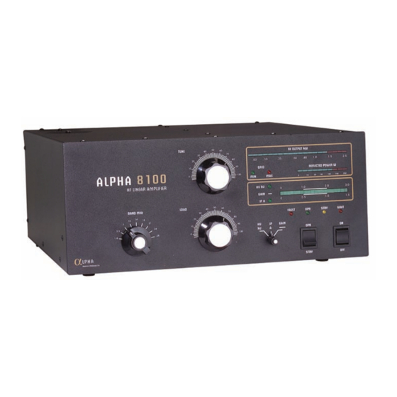
Press OFF to remove primary AC power. OPR/STBY Operate (OPR) places the amplifier in-line. With the 8100 off, in standby(STBY), or in warm-up with the WAIT LED lighted, the amplifier is bypassed and the exciter is connected directly to the antenna. Metering LEDs Separate bargraphs provide instantaneous full-time display of peak values. -
Page 39: Alc
ALC control is necessary. It is only necessary to set the drive power from the radio as detailed in this manual. 6.3.5 Turning On The Amplifier Please Note: Every time the ALPHA 8100 is powered up there is a built-in 150 second warm up wait. 1. Place the OPR/STBY switch to STBY (standby). -
Page 40: Tuning The Amplifier
28.6 29.7 *Each ALPHA 8100 shipped from our factory will include an individual table showing the tune and load settings we used to achieve full output power on that amplifier into an AP 2100, a 50-ohm dummy load. These settings usually vary slightly from those in the manual. - Page 41 OPR/STBY switch to STBY! Verify all connections and cables, turn the amplifier switch to OPR and proceed with the tuning procedure. Alpha Radio Products recommmended tune up procedure. “Dip and Load” Method Tuning up for Operation at 1,500 W RF Output.
- Page 42 10. Touch up the TUNE for maximum power output. 11. The ALPHA 8100 is now correctly tuned to deliver 1500 W RF output on SSB, CW, FSK, SSTV and FM. The GAIN LED normally fluctuates during modulation or keying. Illumination of the first red LED on the RF OUTPUT bargraph indicates output has exceeded 1500 W.
-
Page 43: Normal Use
6.4 Normal Use 6.4.1 Tubes The 4CX800A/GU74b tubes used in the ALPHA 8100 are supplied as a matched pair. They are very rugged and normally operate with a large margin of safety. They should provide outstanding service for many years if not damaged by abuse - such as overdrive or blockage of cooling airflow. -
Page 44: Plate Overcurrent Relay
Should the overcurrent relay trip, remove AC power from the amplifier, then determine and correct the cause of the trip before turning the 8100 on again. This “hard fault” trip circuit does not rely on the microntroller for it’s operation, and will protect the amplifier even if the processor has been damaged or is malfunctioning. -
Page 45: Standard Maintenance Tasks
There are no user-accessible lubrication points in the amplifier. Do not apply oil or grease to any of the components. The exterior of the ALPHA 8100 may be cleaned with a mild household liquid detergent. Do not use chemical solvents, as these may severely damage the front panel or cabinet finish. - Page 46 ALPHA 8100 OPERATING MANUAL www.alpharadioproducts.com...
-
Page 47: Troubleshooting Hints
7 Troubleshooting Hints 7.1 Normal Troubleshooting 8100 will not turn on; nothing happens when ON switch is pushed. Problem Correction 1) External AC wiring, fuse or circuit breaker Check & correct wiring, replace fuse, or reset may be open. circuit breaker. - Page 48 Amplifier operates but green GRID LED will not light and plate current is low; transceiver does not seem to be able to drive amplifier to its rated RF output power level. Problem Correction 1) Input RF load resistor or bias circuitry Contact Alpha Customer Service. damaged. ALPHA 8100 OPERATING MANUAL www.alpharadioproducts.com...
- Page 49 4) Poor station RF ground. Be sure the amplifier and transceiver have a proper RF ground. Correct if necessary. Low frequency (60 Hz) audio hum on transmitted signal. ALPHA 8100 OPERATING MANUAL www.alpharadioproducts.com...
-
Page 50: Troubleshooting Using The Serial Port
2) Dynamic (magnetic) microphone located All dynamic microphones pick up some within about two feet of 8100 power magnetically coupled hum from the external transformer. field of nearby power transformers. In cases... - Page 51 The checksum calculation begins after this character. APA00 Short for Alpha Power Amplifier type 00. This indicates the sentence is from an Alpha product, an amplifier. Type 00 sentences are frequently used for identification. This is the beginning of the “payload”...
- Page 52 The checksum calculation begins after this character. APA01 Short for Alpha Power Amplifier type 01. . This indicates the sentence is from an Alpha product, an amplifier. Type 01 sentences are frequently used for telemetry.
- Page 53 8DA3 Fletcher checksum (FCS) of the payload portion. The FCS is a two-byte quantity calculated over the payload portion of the sentence, according to the following pseudocode: sum1=0 sum2=0 for n=0 to (length(payload))-1 sum 1= sum1 +Payload(n) sum2=sum2+sum1 next n The result is displayed as hexadecimal ascii. ALPHA 8100 OPERATING MANUAL www.alpharadioproducts.com...
- Page 54 Send “V” to cause this sentence to be emitted continuously. ALPHA 8100 OPERATING MANUAL www.alpharadioproducts.com...
-
Page 55: Glossary
AWG- American wire gauge Continuous wave Decibel EBS- Electronic bias control Exciter- The radio that provides RF drive for the 8100 to operate FCC- Federal Communications Commission Frequency modulation FSK- Frequency-shift keying High frequency (3 to 30 MHz) High voltage... - Page 56 Standing wave ratio. A measure of antenna and feedline efficiency. T/R- Transmit / Receive UHF- Ultra high frequency (300-3,000 MHz) United States VAC- Volts of alternating current VDC- Volts of direct current VSWR- Voltage standing wave ratio ALPHA 8100 OPERATING MANUAL www.alpharadioproducts.com...
Need help?
Do you have a question about the 8100 and is the answer not in the manual?
Questions and answers