Table of Contents
Advertisement
CAUTION, MICROWAVE RADIATION ................................................................................................................. 1
WARNING .............................................................................................................................................................. 1
PRODUCT SPECIFICATIONS ............................................................................................................................. 2
GENERAL INFORMATION .................................................................................................................................... 2
APPEARANCE VIEW ........................................................................................................................................... 3
OPERATION SEQUENCE .................................................................................................................................... 4
FUNCTION OF IMPORTANT COMPONENTS .................................................................................................... 5
SERVICING .......................................................................................................................................................... 6
TEST PROCEDURE ............................................................................................................................................. 8
TOUCH CONTROL PANEL ................................................................................................................................. 14
COMPONENT REPLACEMENT AND ADJUSTMENT PROCEDURE ............................................................... 18
MICROWAVE MEASUREMENT ........................................................................................................................ 24
WIRING DIAGRAM ............................................................................................................................................. 25
PICTORIAL DIAGRAM ....................................................................................................................................... 26
CONTROL PANEL CIRCUIT ............................................................................................................................... 27
PRINTED WIRING BOARD ................................................................................................................................. 28
PARTS LIST ....................................................................................................................................................... 29
SERVICE MANUAL
MODEL
In interests of user-safety the oven should be restored to its original
condition and only parts identical to those specified should be used.
TABLE OF CONTENTS
SHARP CORPORATION
MICROWAVE OVEN
R-3S56
R-3S56
S9510R3S56PX/
Page
Advertisement
Table of Contents

Related Manuals for Sharp R-3S56


Summary of Contents for Sharp R-3S56
-
Page 1: Table Of Contents
R-3S56 SERVICE MANUAL S9510R3S56PX/ MICROWAVE OVEN R-3S56 MODEL In interests of user-safety the oven should be restored to its original condition and only parts identical to those specified should be used. TABLE OF CONTENTS Page CAUTION, MICROWAVE RADIATION ......................... 1 WARNING ................................ - Page 2 R-3S56...
-
Page 3: Caution Microwave Radiation
MICROWAVE OVEN R-3S56 GENERAL IMPORTANT INFORMATION APPEARANCE VIEW This Manual has been prepared to provide Sharp Corp. Service engineers with Operation and Service Information. OPERATING SEQUENCE It is recommended that service engineers carefully study the entire text of this manual, so they will be qualified to render satisfactory customer service. -
Page 4: Product Specifications
R-3S56 PRODUCT SPECIFICATIONS ITEM DESCRIPTION Power Requirements 220 Volts 50 Hertz Single phase, 3 wire earthed Power Consumption 1.06 kW, Approx. 4.9A Power Output 700 watts nominal of RF microwave energy (IEC 705) Operating fequency 2450 MHz Case Dimensions Width 450 mm... -
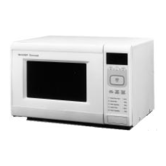
Page 5: Appearance View
R-3S56 APPEARANCE VIEW 1. Ventilation opening 2. Oven lamp 3. Door hinges 4. Door safety latches 5. See through door 6. Coupling 7. Door open button 8. Touch control panel 9. Digital read-out 10.Wave guide cover 11.Power supply cord 12. Earth wire TOUCH CONTROL PANEL a. -
Page 6: Operation Sequence
R-3S56 OPERATION SEQUENCE OFF CONDITION The circuits to the power transformer, fan motor and turntable motor are cut off when the 1st. latch switch, Closing the door activates all door interlock switches 2nd. latch switch, and stop switch are made open. The (1st. -
Page 7: Function Of Important Components
R-3S56 FUNCTION OF IMPORTANT COMPONENTS DOOR OPEN MECHANISM 2. If the wire harness or electrical components are short- circuited, this fuse blows to prevent an electric shock or The door is opened by pushing the open button on the fire hazard. -
Page 8: Servicing
3D checks and re-examine the connections to the component being tested. Sharp recommend that wherever possible fault-finding is carried out with the supply disconnected. It may in, some cases, be necessary to connect the supply after... - Page 9 R-3S56 CK = Check / RE = Replace TEST PROCEDURE A B C D E E E E F G G G H H I J L M RE CKCKRE CKCKCKCKCK POSSIBLE CAUSE DEFECTIVE PARTS PROBLEM CONDITION Home fuse blows when power supply cord is plugged into wall outlet.
-
Page 10: Test Procedure
R-3S56 TEST PROCEDURES PROCEDURE LETTER COMPONENT TEST MAGNETRON TEST NEVER TOUCH ANY PART IN THE CIRCUIT WITH YOUR HAND OR AN INSULATED TOOL WHILE THE OVEN IS IN OPERATION. CARRY OUT 3D CHECKS. Isolate the magnetron from high voltage circuit by removing all leads connected to filament terminal. - Page 11 R-3S56 TEST PROCEDURES PROCEDURE LETTER COMPONENT TEST 6. Measure the final water temperature. (Example: The final temperature T2 = 21°C) 7. Calculate the microwave power output P in watts from above formula. Initial temperature ....................T1 = 11°C Temperature after (60 + 2) = 62 sec..............T2 = 21°C Temperature difference Cold-Warm..............
- Page 12 R-3S56 TEST PROCEDURES (CONT'D) PROCEDURE COMPONENT TEST LETTER CARRY OUT 4R CHECKS. NOTE: FOR MEASUREMENT OF THE RESISTANCE OF THE RECTIFIER, THE BATTERIES OF THE MEASURING INSTRUMENT MUST HAVE A VOLTAGE AT LEAST 6 VOLTS, BECAUSE OTHERWISE AN INFINITE RESISTANCE MIGHT BE SHOWN IN BOTH DIRECTIONS.
- Page 13 R-3S56 TEST PROCEDURES (CONT'D) PROCEDURE COMPONENT TEST LETTER If incorrect readings are obtained, replace the temp. fuse or thermal cut-out. An open circuit temperature fuse (MAG.) indicates that the magnetron has overheated, this may be due to resistricted ventilation, cooling fan failure.
- Page 14 R-3S56 TEST PROCEDURES (CONT'D) PROCEDURE COMPONENT TEST LETTER d) The corresponding segments of all digits do not light up or they continue to light up. e) Wrong figure appears. f) A certain group of indicators do not light up. g) The figure of all digits flicker.
- Page 15 R-3S56 TEST PROCEDURES (CONT'D) PROCEDURE COMPONENT TEST LETTER STEPS OCCURANCE CAUSE OR CORRECTION The rated voltage is not applied to POWER Check supply voltage and oven main unit. terminal of CPU connector (CN-A) The rated voltage is applied to primary side of Power transformer or secondary circuit defective.
-
Page 16: Touch Control Panel
R-3S56 TOUCH CONTROL PANEL ASSEMBLY OUTLINE OF TOIUCH CONTROL PANEL Control Unit Control unit consists of tact switches, LSI, power source circuit, synchronizing signal circuit, ACL circuit, buzzer circuit and indicator circuit. 1) Tact Switches The tact switches are composed of a matrix, signals generated in the LSI are sent to the tact switches through . - Page 17 R-3S56 DESCRIPTION OF LSI LSI(IZA588DR): The I/O signal of the LSI(IZA588DR) is detailed in the following table. Pin No. Signal Description Internal clock oscillation frequency control output. Output to control oscillation input of X Internal clock oscillation frequency input setting.
- Page 18 R-3S56 Pin No. Signal Description Signal coming from touch tact switch. When either one of resistor R9 line switches on switch matrix is touched, a corresponding signal will be input into R8 Signal coming from touch tact switch. When either one of resistor R9...
- Page 19 R-3S56 SERVICING 1. Precautions for Handling Electronic Components B. On some models, the power supply cord between the This unit uses CMOS LSI in the integral part of the touch control panel and the oven proper is long enough circuits. When handling these parts, the following pre- that they may be separated from each other.
-
Page 20: Component Replacement And Adjustment Procedure
R-3S56 COMPONENT REPLACEMENT AND ADJUSTMENT PROCEDURE WARNING: Avoid possible exposure to microwave energy. Please follow the instructions below before operating the oven. 1. Disconnect oven from power supply. 1. Door does not close firmly. 2. Make sure that a definite” click” can be heard when the 2. -
Page 21: Control Panel Removal
R-3S56 CONTROL PANEL REMOVAL 1. CARRY OUT 3D CHECKS remaining adhesive on the control panel frame 2. Disconnect the leads from the control unit. surfaces completely with alcohol and so on. 2. When attaching the key sheet to the control 3. - Page 22 R-3S56 CAUTION: Re-install the chassis support to the oven cavity front plate with the one (1) screw. • Do not hit the fan blade strongly when installed because the bracket may be transformed. Install the main wire harness into the hole of the fan •...
-
Page 23: Power Supply Cord Replacement
Figure C-3(b). Turntable Motor Cover Re-install Figure C-3(a). Turntable Motor Cover Removal Re-install Washer 1. Remove the any sharp edges on the turntable motor Washer cover and the bottom plate L with the cutting pliers. O-ring Apply the grease hear 2. -
Page 24: Door Replacement And Adjustment
R-3S56 1ST.,2ND. LATCH SWITCH ,STOP SWITCH AND MONITOR SWITCH REMOVAL LATCH HOOK 1. CARRY OUT 3D CHECKS. Post 2. Remove the control panel assembly referring to MONITOR SWITCH "CONTROL PANEL REPLACEMENT". Post 3. Remove the switch lever from the oven cavity front plate 1ST. - Page 25 R-3S56 DOOR ADJUSTMENT 5. Remove the door frame from the door panel. When removing and/or loosening hinges such as in door 6. Release the latch spring from the tabs of the latch head. replacement, the following adjustment criteria are taken.
-
Page 26: Microwave Measurement
R-3S56 MICROWAVE MEASUREMENT Recommended instruments are: After adjustment of door latch switches, monitor switch and NARDA 8100 doorare completed individually or collectively, the following leakage test must be performed with a survey instrument NARDA 8200 and it must be confirmed that the result meets the require- HOLADAY HI 1500 ments of the performance standard for microwave oven. -
Page 27: Wiring Diagram
R-3S56 SCHEMATIC NOTE: CONDITION OF OVEN 1. DOOR CLOSED. 2. CLOCK APPERARS ON DISPLAY NOTE: " " indicates components with potential above 250V. Figure O-1 Oven Schematic-OFF Condition SCHEMATIC NOTE: CONDITION OF OVEN 1. DOOR CLOSED. 2. COOKING TIME PROGRAMMED 3. -
Page 28: Pictorial Diagram
R-3S56... -
Page 29: Control Panel Circuit
R-3S56... -
Page 30: Printed Wiring Board
R-3S56 ZD10 (ZD3) (R6) (J3) Figure S-3. Printed Wiring Board... -
Page 31: Parts List
R-3S56 PARTS LIST ∆ Note: The parts marked " " may cause undue microwave exposure. The parts marked "*" are used in voltage more than 250V. REF. NO. PART NO. DESCRIPTION Q'TY CODE ELECTRIC PARTS 1- 1 FH-DZA051WRK0 High voltage rectifier assembly... - Page 32 R-3S56 ∆ Note: The parts marked " " may cause undue microwave exposure. The parts marked "*" are used in voltage more than 250V. REF. NO. PART NO. DESCRIPTION Q'TY CODE SP40 RALM-A014DRE0 Buzzer (PKM22EPT) SW1-7 QSW-PA004DRE0 Tact switch RTRNPA087DRE0...
- Page 33 R-3S56 ∆ Note: The parts marked " " may cause undue microwave exposure. The parts marked "*" are used in voltage more than 250V. REF. NO. PART NO. DESCRIPTION Q'TY CODE SCREWS, NUTS AND WASHERS 7- 1 XWUSE40-05000 Washer; 4mm X 0.5mm...
- Page 34 R-3S56 OVEN AND CABINET PARTS 4-20 7-10 4-23 7-17 4-18 1-20 7-18 7-12 1-10 4-28 7-17 4-20 7-10 7-12 4-29 1-19 7-16 6-10 4-27 4-14 4-21 7-11 7-12 6-11 4-19 7-10 6-12 4-10 7-10 4-16 1-16 4-13 4-22 4-26 4-15...
- Page 35 R-3S56 CONTROL PANEL PARTS x 10 3-2-1 DOOR PARTS 7-13 7-13 MISCELLANEOUS Actual wire harness may be different from illustration. 80 ± 5...
-
Page 36: Packing And Accessories
DOOR PROTECTION SHEET (SPADPA204WRE0) POLYETHYLENE BAG (SSAKHA014WRE0) TURNTABLE TRAY COOKING WEAR (PSRA-A026WRP0) EARTH CAUTION COOK BOOK (THAI) MICROWAVE OVEN ROLLER STAY INTO THE OVEN CAVITY TRAY PAD ASSEMBLY (SPADFA370WRE0) PACKING CASE Not replaceable items. (SPAKCC686WRE0) '95 SHARP CORP. (09U0.06E) Printed in Japan...
Need help?
Do you have a question about the R-3S56 and is the answer not in the manual?
Questions and answers