
Related Manuals for MRC TES - 3060


Summary of Contents for MRC TES - 3060
-
Page 1: Instruction Manual
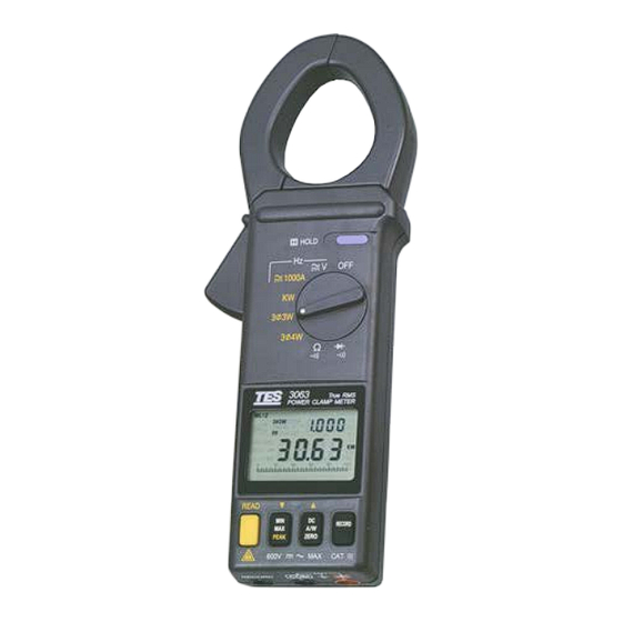
DATALOGGING AC/DC CLAMP POWER METER TES - 3060/3063 INSTRUCTION MANUAL PLEASE READ THIS MANUAL CAREFULLY BEFORE OPERATION 3, Hagavish st. Israel 58817 Tel: 972 3 5595252, Fax: 972 3 5594529 mrc@mrclab.com MRC.7.14... -
Page 2: Table Of Contents
CONTENTS I. SAFETY INFORMATION ............1 II. TECHNICAL SPECIFICATIONS..........3 2-1 Environment Conditions ...........3 2-2 Maintenance ..............3 2-3 Features................3 2-4 General Specifications............4 2-5 Measurement Specifications ..........5 III. PARTS & CONTROLS.............7 3-1 Description of Parts & Control ..........7 IV. AC+DC POWER MEASUREMENT ........11 4-1 AC+DC 1φ2W Power(W) and Power Factor (PF) Measurement ..............11 4-2 3φ3W AC+DC Power Measurement.......13... -
Page 3: Safety Information
I. SAFETY INFORMATION Read the following safety information carefully before attempting to operate or service the meter. To avoid damages to the instrument do not exceed the maximum limits of the input values shown in the technical specification tables. Do not use the meter or test leads if they look damaged. Use extreme caution when working around bare conductors or bus bars. -
Page 4: Technical Specifications
II. TECHNICAL SPECIFICATIONS 2-1 Environment Conditions: Installation categories III Pollution degree 2 Altitude up to 2000 meters Indoor use only Relatively humidity 80% max. Operation ambient 0 〜50℃ 2-2 Maintenance Repairs or servicing not covered in this manual should only be performed by qualified personnel. Periodically wipe the case with a dry cloth. -
Page 5: General Specifications
2-4 General Specifications Maximum voltage between any terminal and earth ground : 600Vrms. Numerical dual display : 4 digit liquid crystal display (LCD) maximum reading 9999. Bargraph display : 40 segments. Battery life : 30hr approx. (Alkaline). Low battery indication :... -
Page 6: Measurement Specifications
2-5 Measurement Specifications Accuracy are•±(• of reading • number of digits) at 18• to 28• ( 64• to 82•) with relative humidity to 80•. TRUE power & Apparent power measurement Frequency Overload Input Resolution Accuracy range protection V<130V , A<150A V>130V , A<150A 0.01 45Hz 〜... -
Page 7: Audible Continuity
Peak indication Range Resolution Accuracy Overload protection 20A~80A 0.1A ± (10% + 10) 1100A ± ( 6% + 10) 80A~1000A 0.1A 1100A ※ Peak detect acquisitions time ≦ 1ms Peak indication Range Resolution Accuracy Overload protection ± (10% + 10) 20V~80V 0.1V 600Vrms... -
Page 8: Parts & Controls
III. PARTS & CONTROLS 3-1 Description of Parts & Control HOLD 1000A 3 3W 3 4W W L 1 23 ME M R E A D P P- H O L D MA X 3 3 W 3 4 W KV A PF lead lag R E C O R D... - Page 9 (1). Transformer jaws Pick up the AC and DC current flowing through the conductor. (2). Jaw opening trigger. (3). Data Hold button Press it once to hold the measured value and store the value in memory. Press again to release hold function. (4).
- Page 10 Press the button once to zero the A or KW reading. (8). RECORD button • Single Data Record The clamp meter can store 25 data record in memory. Once the button is pressed, the data number and RECORD symbol will be shown on LCD. If the memory is full, the FULL signal will be shown on LCD when the record button is pressed.
- Page 11 W L 1 23 W L 1 23 ME M ME M R E A D R E A D P P- P P- H O L D H O L D MA X MA X 3 3 W 3 3 W 3 4 W 3 4 W KV A...
-
Page 12: Ac+Dc Power Measurement
AC+DC POWER MEASUREMENT WARNING Wait until “- - - -” symbol is shown on LCD before clamping on to any conductor and pressing on the ZERO button to zero any residual magnetic field in the jaws. 4-1 AC+DC 1 φ 2W Power(W) and Power Factor (PF) Measurement HOLD 1000A 3 3W... - Page 13 Connect the test probe of COM (black) terminal to the neutral line. Connect the test probe of V (red) terminal to the power line. Clamp the conductor where V (red) terminal is connected. The power clamp will automatically select the appropriate range. Read the Watt and PF values displayed on the LCD.
-
Page 14: Φ 3W Ac+Dc Power Measurement
4-2 3 φ 3W AC+DC Power Measurement HOLD 1000A 3 3W 3 4W W L 1 2 3 3 W W L 1 2 W L 1 2 3 3 W 3 3 W 600V 600V MAX CAT (Figure-4) - Page 15 HOLD 1000A 3 3W W L 23 3 4W W L 23 3 3 W 3 3 W W L 23 3 3 W 600V 600V MAX CAT (Figure-5) W L 1 23 H O L D 3 3 W 600V MAX CAT (Figure-6)
- Page 16 First, measure W (refer to figure 4). RS(L1L2) a. Turn the power on without clamping to any wire. b. Set the rotary switch at 3 φ 3W, and W symbol will appear to instruct users to take measurement of W RS(L2L1) c.
- Page 17 The power clamp will process those two sets of data (W ), and show the result on the LCD. W symbol will L123 be shown to indicate the watt of 3 φ 3W power. At this moment, the watt of 3 φ 3W power is stored into the memory.
-
Page 18: Φ 4W Ac+Dc Power Measurement
4-3 3 φ 4W AC+DC Power Measurement HOLD 1000A 3 3W 3 4W W L 1 W L 1 3 4 W 3 4 W W L 1 3 4 W 600V 600V MAX CAT (Figure-7) HOLD 1000A 3 3W 3 4W W L 2 3 4 W... - Page 19 HOLD 1000A 3 3W 3 4 W 3 4W 3 4 W 3 4 W 600V 600V (Figure-9) W L 1 23 H O L D 3 4 W 600V MAX CAT (Figure-10)
- Page 20 First, measure W (refer to figure 7). R(L1) R(L1) a. Turn the power on without clamping on to any wire. b. Set the rotary switch at 3 φ 4W . c. Insert the test leads into the input jack. d. Connect the neutral line to the COM (black) terminal. e.
-
Page 21: Φ 3W Power Measurement
d. The power clamp will automatically select proper range. e. Wait until the reading is stable (about 3~6 seconds), press the YELLOW button, and W symbol will disappear. The power clamp will process these three sets of data (W ) and show the result on the LCD. WL symbol will be shown to indicate the watt of 3 φ... - Page 22 HOLD 1000A 3 3W 3 4W W L 1 2 3 3 W W L 1 2 W L 1 2 3 3 W 3 3 W 600V 600V (Figure-11)
- Page 23 HOLD 1000A W L 23 W L 23 3 3 W 3 3W 3 4W 3 3 W W L 23 3 3 W 600V 600V MAX CAT (Figure-12) W L 1 23 H O L D 3 3 W 600V MAX CAT (Figure-13)
- Page 24 1 φ 3W power measurement is similar to 3 φ 3W unbalanced power measurement except the nomenclature is different. Two measurements of W and W are required. RS(L1G) TS(L2G) First, measure W (refer to figure 11). RS(L1G) a. Turn the power on without clamping to any wire. b.
-
Page 25: Operating Instruction
V. OPERATING INSTRUCTION 5-1 AC+DC Voltage Measuremen HOLD 1000A 3 3W 3 4W 600V (Figure-14) WARNING: Maximum input is 600V. Do not attempt to take any voltage measurement that exceeds these limits. Exceeding these limits could cause electrical shock and damage to the clamp meter. -
Page 26: Ac+Dc Current Measurement
5-2 AC+DC Current Measurement HOLD 1000A 3 3W 3 4W 600V 600V (Figure-15) Set the rotary switch at A (refer to figure 15). Press the ZERO button once to zero the reading and LCD will show “- - - -” sign. Press the trigger to open the jaw and fully enclose the conductor to be measured. -
Page 27: To Improve Power Factor Of A 3Φ4W Power System
5-3 To Improve Power Factor of a 3 φ 4W Power System Calculate KVAR , KVAR , and KVAR values of R(L1) S(L2) T(L3) each phase. Based upon the calculated values, users can purchase required 3 φ or 1 φ capacitor at rated voltage and frequency to improve power factor. -
Page 28: To Improve Power Factor Of A 1Φ2W Power System
5-5 To Improve Power Factor of a 1 φ 2W Power System Calculate KVAR value of a 1 φ 2W power system. Based upon the calculated value, users can purchase required capacitor at rated voltage and frequency to improve power factor. If value of capacitance is needed, users can obtain the value by the following equation. -
Page 29: Diode Test & Continuity Measurement
HOLD 1000A 3 3W 3 4W 600V (Figure-16) Note : Continuity test is available to check open/short of the circuit. 5-7 Diode Test & Continuity Measurement Connect red test lead to the " • " terminal and black test lead to the " COM" terminal. Set range switch to the diode test position "... -
Page 30: Operation Of Data Record And Read
Set Function / Range Switch to desired •A or •V range. Set the clamp Meter into the " PEAK HOLD " mode by pushing the "YELLOW" button. The LCD will display " P+ P- ". Press the “PEAK” button to enter PEAK mode. LCD will display “P+ MAX”... -
Page 31: Battery Replacement
Clear data logger To clear the memory of the meter, power off the meter, then hold RECORD button and then power on it until the LCD shows CLr. VI. BATTERY REPLACEMENT WARNING To prevent electrical hazard or shock, turn off clamp meter and disconnect test leads before removing back cover.
Need help?
Do you have a question about the TES - 3060 and is the answer not in the manual?
Questions and answers