
Related Manuals for Onwa KR-1338


Summary of Contents for Onwa KR-1338
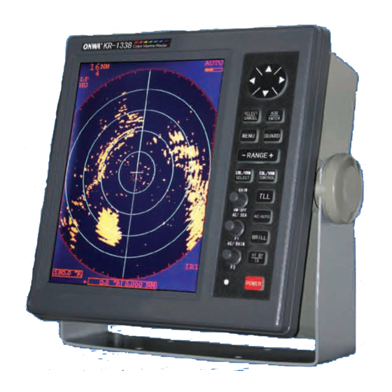
- Page 1 KR-1338/1668 KR-1338/1668 SERVICE MANUAL Î ¬ Ð Þ Ê Ö ² á 10.4 TFT COLOR MARINE RADAR...
-
Page 3: Table Of Contents
TABLE OF CONTENTS 1.GENRAL 1.1 Outline 1.2 Boards & Major Components 1.3 Specifications 2.BLOCK DESCRIPTION 2.1 Overview 2.2 Display Unit Block Diagram of Power Supply Block Diagram of Processor PCB Main 0910 2.3 Transceiver Unit Block Diagram of IF 0711 Block Diagram of Modulator 2.4 Different Points of Similar PCBs 3. - Page 4 5.TROUBLESHOOTING 5.1 Outline 5.2 Troubleshooting Flow Charts 5.3 Message Indication Display Unit Exploded view Scanner Unit Exploded View Schematic circuit diagram...
-
Page 5: Genral
The table below shows the major specifications of the each model. The same program is installed on all models, but the menu setting through factory menu is different between the models. Functions KR-1338 KR-1668 Maximum range 36 NM 64 NM... -
Page 6: Boards & Major Components
1.2 Boards & Major Components Board KR-1338 KR-1668 PROCESSOR Board MAIN 0910 POWER SUPPLY Board PWR 0913 DISPLAY UNIT FILTER Board FIL 0912 KEY 0912 PANEL Board MOD 0904A MOD 0904B MODULATOR Board IF AMP Board IF 0711 RTB Board... -
Page 7: Specifications
24 rpm nominal Scanner Housing Stureruct Radome Open nominal 0.9 m 1.0 m Standard Compass Safe Distance Steering 0.7 m 0.74 m KR-1338-SME-3 TRANCEIVER KR-1338 KR-1668 Magnetron MAF1421B/MSF1421 MAF1421/MAF1422B Frequency &Modulation 9410 M z 30M z,P0N 6 kW nominal Peak Output Power 4 kW nominal 0.08... -
Page 8: Display Unit
DISPLAY UNIT KR- 1338 KR-1668 Picture Tube 10.4 LCD(LED backlight ,32 bit TFT color LCD) KR-1338:36 nm KR-1668:64 nm Range Scale(nm) 0.125 0.25 0.5 0.75 1 1.5 2 3 4 6 8 12 16 24 36 48 64 Range Ringe Interval 1/16 0.125 0.125 0.25 0.25 0.5 0.5 1 1 2 2 3 4 6 12 12 16... - Page 9 ENVIRONMENTAL CONDITIONS KR-1338 KR-1668 Scanner Unit to +70 Ambient Temperature Display Unit to +55 Humidity Relative humidity 93% 2% or less at +40 Vibration -IEC 60945 KR-1338-SMJ-6 POWER SUPPLY & POWER CONSUMPTION KR-1338 KR-1668 10.5 V to 40.0V DC Power...
-
Page 10: Block Description
2. BLOCK DESCRIPTION 2.1 Overview The simpified block diagram of the system is illustrated below. Scanner Unit Antenna Display Unit Mag. HD.BP Mod. Video Processor Trigger RF Module Panel Power Ship s mains Nav. Gyro The trigger pulse from the PROCESSOR Board is delivered to the MODULATOR Board, oscillates the magnetron, and then radar wave is emitted from the radiator. -
Page 11: Display Unit
2.2 Display Unit Power Supply Circuit (PWR 0913) The constant voltage generator Q1 is in operation even when power switch is off, ship s mains is supplied. The power supply circuit is basically consists of a main inverter and a sub inverter. The main inverter derives the isolated line voltages +12 V/ANT+12 V and -12 V/ANT -12 V from the main input. - Page 12 Qverload on +5 V and + 32 V line is detected by U6. Overload on +12 V(MOTOR+) line is detected by U7. When the +5 V and + 32 V line is reduced by a heavy load, U6 or U7 becomes condctive and consequently disables the PWM controller thro- ugh Q6, Q7 and Q8.
-
Page 13: Block Diagram Of Power Supply
BLOCK DIAGRAM OF POWER SUPPLY... -
Page 14: Block Diagram Of Processor Pcb Main 0910
BLOCK DIAGRAM OF PROCESSOR PCB MAIN 0910... - Page 15 AUTOMATIC TUNING There are two types of automatic tuning: peak search and short search. The tuning voltage differs from model to model. KR-1338/1668 : 5 V to 28 V Peak search: Tuning voltage (TUNING), point in the figure below, is searched in the tuning voltage range 5V to 28V.
-
Page 16: Manual Tuning
TUNING INDICATOR After tuning adjustment, peak TUNING IND voltages, , and in the figure on page are stored on to EEPROM. The automatic and manual tuning point is also memorized. Using these data, the tuning indicator extends more than 80% on ALL TX pulses. Note that the extension on short pulse is shorter than on long pulse. - Page 17 Heading and NAV data Heading data in NMEA format HEADING DATA (HDT, HDG, HDM, VHW)and NAV data (NMEA-0183)can be input from any NMEA input connection. THE data from the KEY board(KEY 0912) to P8#3 of MAIN board . NOTE: 1.If only one NMEA signal input may select any connection, if several connections have time the signal input, be please main and the most commonly used signal meets in the connection 1, because the complete signal's input is 1 comes the synchronization by the connection, i.e.
-
Page 18: Transceiver Unit
2.3 Transceiver Unit The following description is for reference only. As a general rule of thumb, the radar requires better noise figure (NF) and better dynamic range. Both factors, however, are reciprocal. The NF affects long range performance, while the dynamic range dose short range performance. To improve noise figure, amplifier and MBS circuit into the MIC, RU-9360. -
Page 19: Block Diagram Of If 0711
BLOCK DIAGRAM OF IF 0711... - Page 20 Modulator PRINCIPLE OF FET SWITCHING MODULATOR High voltage is charged into C through R while the magnetron is inactive. When the trigger is applied to the power MOS-FET, the FET turns on and the high voltage appears at the primary winding of the pulse transformer. This transformer boots the voltage, which makes the magnetron oscillate.
-
Page 21: Block Diagram Of Modulator
BLOCK DIAGRAM OF MODULATOR PCB MOD 0904... -
Page 22: Different Points Of Similar Pcbs
2.4 Different Points of Similar PCBs 1. How to set SPU (MAIN 0910) Board This board is set at factory for use in the KR-1338. For use in the or 1668, change the factory menu as below. While pressing and holding down the GAIN(HM-OFF) control, press the [MENU] key five times to display the factory menu. -
Page 23: Adjustment
3. ADJUSTMENT WARNING IMPORTANT! SAFETY INFORMATION Be sure to read all the safety information which follows before perfoming any adjustment. Hazardous Voltage This equipment uses high voltage electricity which can SHOCK, BURN or cause DEATH Always make sure the electrical power is turned off before attempting to change a component or inspecting the inside of the equipment. -
Page 24: Adjustment Of Display Unit
3.1 Adjustment of Display Unit Display Unit, Front side of view Power Connector OPTION DJ-1 Connector Fuse Holder UPGRADE NMEA-1 Connector NMEA-2 Connector Display Unit, Rear side of view... - Page 25 Inside of Display Unit, LCD Inside of Display Unit, Processor PCB...
- Page 26 Inside of Display Unit, Power PCB...
- Page 27 12.0 to 12.3 V DJ1-1(+)-DJ1-20(-) KR-1338-SME-8 Output signals from DJ-1 connector Test Item Ratings Test Point Remarks Approx. 5 V to 28 V(KR-1338/1948/ Antenna Unit discon- TUNE DJ1-6(+) -DJ1-20(-) ected TX, Auto tuning 1968) Short pulse: 0 to 1.0V(L) P/L A...
-
Page 28: Location Of Parts On Main 0910
S: 2.0V to 2.3V TX Condition S: 2.6V to 2.8V GAIN VR: MAX STC Curve S: 3.0V to 3.2V STC VR: MAX S: 4.0V to 4.5V -4 Vpp VIDEO Preset (Neg. Polarity, main bang level) TX Condition 8 to 12V TX TRIGGER KR-1338-SMC-10... -
Page 29: Video Signal Adjustment
VIDEO Signal adjustment VIDEO signal adjustment is carried out in the processor board. This is a simplified block diagram of the video amplified circuit. VIDEO AMP ANTI-LOG Clutter level Video level Gain preset Video Out VIDEO IN < 2 Curve VIDEO GAIN LEVEL... - Page 30 Gain preset Conditions A/C AUTO A/C SEA fully clockwise A/C RAIN fully counterclockwise GAIN fully Clockwise Scanner [INSTALLATION SETUP 1] menu 4. Ant on Tx : STOP Table 3-6 Gain preset Check Point Rating Adjuster TP3 on SPU pcb (trigger at TP1) = 0.04 to 0.06V STC curve...
- Page 31 ANT height setting Antenna height (STC curve adjustment) should be set Radar at installation to match the STC curve with installation conditions. This is especially important when sea conditions changes over time - rotation of the STC VR may erase both sea clutter and legitimate targets if the STC curve is not suitable.
-
Page 32: Location Of Parts On Pwr-0913
Inverter Frequency 85.5 to 94.5 KHz +12 V 12.1 to 12.3 V VR 1 TP 31 4.9 to 5.2 V +5 V TP 32 J1 #2(-) -11.6 to -12.8 V +12 V J1 #7(GND) J1 #3(+) 30.0 to 35.0 V +32 V J1 #7(GND) KR-1338-SME-11... -
Page 33: Adjustment Of Scanner Unit
3.2 Adjustment of Scanner Unit Location of PCBs in Scanner Unit KR 1338 Magnetron V801 (NJT1968) MSF1421 IF AMP Board MODULATOR IF0711 MOD0904 Read Swith Scanner Motor B801 S801 BM-9256 Inside of Scanner Unit... -
Page 34: Location Of Parts On Mod-0904
TX-HV TX: 290 to 330 Vdc(Long) TP803 +14V ST-BY 13 to 17 Vdc Mag. Heater VR801 ST-BY 7.4 to 7.6 Vdc 0.25 to 1.2 Vdc(Short) TX (Long) VR802 Mag. Current 0.7 to 1.2 Vdc(Medium) Condition 0.9 to 1.1 Vdc(Long) KR-1338-SMC-12... -
Page 35: Location Of Parts On If-0711
For factory adjustment TP 5 T3, T4 TP 7 +9 V 8.7 to 9.3 Vdc TP 8 +5 V 4.7 to 5.3 Vdc TP 9 -9 V -8.7 to -9.3 Vdc -5 V TP 10 -4.7 to -5.3 Vdc KR-1338-SME-13... -
Page 36: Location Of Pcbs In Transceiver Module (Kr-1668)
Location of PCBs in Transceiver Module (KR-1668) IF MAP Board IF0711 U801 Magnetron V801 Transceiver Module BEARING SIG GEN Board HBP0904 TP803 J701 MODULATOR Board MOD0904 J812 J811 Transceiver Module, Cover removed... -
Page 37: Location Of Parts On Mod 0904B
TX-HV TX: 300 to 340 Vdc(Long) TP803 +14V ST-BY 13 to 17 Vdc Mag. Heater VR801 ST-BY 7.5 to 7.7 Vdc 0.5 to 1.45 Vdc(Short) TX (Long) VR802 Mag. Current 0.95 to1 .46 Vdc(Medium) Condition 1.15 to 1.35 Vdc(Long) KR-1338-SMC-14... -
Page 38: Location Of Parts On If-0711
For factory adjustment TP 5 T3, T4 TP 7 +9 V 8.7 to 9.3 Vdc TP 8 +5 V 4.7 to 5.3 Vdc TP 9 -9 V -8.7 to -9.3 Vdc -5 V TP 10 -4.7 to -5.3 Vdc KR-1338-SMC-15... -
Page 39: Maintenance
4. MAINTENANCE 4.1 Remarks on Replacement of Major Parts Turn off the power before replacing any parts Do not touch the magnetron while the radar is transmitting. Sufficient high voltage exsts at the magnetron to cause death. MAGENTRON The magnetron emits a strong magnetic field. For this reason, remove wrist watch before performing the replacement and use a non-magnetic screwdriver to dismount the magnetron. -
Page 40: Life Expectancy Of Expendable Parts
4.2 Life Expectancy of Expendable Parts Parts Type Code No. Life expectancy *1 Remarks more than 3000 hrs. BM-9256 000-139-918 KR-1338 Scanner motor more than 5000 hrs. KR-1668 BM-8256 MSF1421 more than 2000 hrs.*2 KR-1338 KR-1338 more than 2000 hrs.*2... -
Page 41: Menu Tree
4.3 Menu tree MENU KEY RINGS(Off,1,2,3,max) EBL OFFSET Off On SHIFT Off On ZOOM Off On MODE HU CU NU TM DISP DATA ECHO TARIL Off On ECHO STRTCH Off ES 1 ES2 .Display ARPA MENU .AllCancel OTHER MENU .Vectpr ref .Vectpr Leng .Panel Dimmer 1,2,3,4... -
Page 42: Troubleshooting
5. TROUBLESHOOTHING 5.1 Outline This chapter provides troubleshooting flow charts and describes error messages. Error messages When there is no bearing pulse signal the display unit shows BP-SIG-MISSING and when is no heading signal, HD-SIG-MISSING. Check the antenna cable when those indications appear. -
Page 43: Troubleshooting Flow Charts
5.2 Troubleshooting Flow Charts Start Press Turn power on. Nothing appears Flow chart 1 on display No echoes nor Flow chart 7 white noise. Abnormal display Flow chart 2 Poor sensitivity. Flow chart 8 No heading data. Flow chart 3 No GAIN,STC, Flow chart 9 FTC effect. - Page 44 Symptom: Nothing appears on the display. Flow chart 1 No(No power) Keys beep when Check in-line fuse. pressed. Yes(Equipment is powered) LCD backlight Faulty LCD assy. lights?. Replace fuse, Check LCD display signal Turn on power J1 on the SPU Board. Check input voltage at connector J1351 on display unit.
- Page 45 Symptom: Display Abnormal Flow chart 2 Check display output signal on MAIN 0910J MAIN 0910 Fault Adjustment Check brill control circuit display brill LCD Fault...
- Page 46 Symptom: No heading data. Flow chart 3 Heading data format. NMEA 0183 s HDT,HDM,HDG Blank Heading data indication Blank Heading data ***.* indication. Check CLK data at HDG connector #3,#4 on ***.* displau unit Turn power off and on. Check HDT,HDM,HDG output setting.
- Page 47 Symptom: No nav data. Flow chart 4 All data shown by asterisks or blank. Nav data indication. Some data shown by asterisks or blank. Check RD NMEA 1 / 2 connector on display unit with oscilloscope. Check nav equipment's output sentences. Faulty nav equipment or interconnection cable.
- Page 48 Symptom: key(S) inoperative. Flow chart 5 Faulty pcb MAIN-0910. Warm up countdown. Faulty VR1 or VR2 on pcb KEY-0912, S1 to S12 Only one key is faulty. on pcb KEY-0912 Faulty lines #10 and #11(KEY 2) of the W301 on Single vertical row only.
- Page 49 Symptom: Antenna dose not rotate. Flow chart 6 Antenna dose not rotate. Stop Menu setting ? Change " Scan stop " setting to "Rotate". (Installation menu) Rotate 0 V (DJ-1 #1) when TX key is pressed. MOTOR(+) on DJ-1 connector. +12 V(DJ-1 #) several seconds after TX key is pressed.
- Page 50 Check for shorted or disc- onnected video signal line Faulty pcb MAIN-0910. between anntena unit and display unit. Disconnected or Faulty cable on video line. shorted. 12 V line on Faulty cable on video line. antenna unit Faulty pcb IF AMP. KR-1338/1668: IF-0711...
- Page 51 Check if level sensitivity (page 5-12) of DJ-1 #16 on display unit is normal No echoes(white noise appears) KR-1338/1668: Faulty pcb IF 0711 9 to 12 V Check TOTAL ON TIME/ TOTAL TX TIME. Faulty pcb MAIN-0910 (No TX trigger)
- Page 52 KR-1668: Faulty pcb MOD-0904B KR-1338: 7.4 to 7.6 Vdc Check magnetron heater KR-1668: 7.5 to 7.7 Vdc voltage at ST-BY. Within rating ? Check magnetron heater KR-1338/1668: VR 801 on pcb MOD-0904 voltage. Within rating ? Faulty magnetron or MIC.
- Page 53 Magnetron usage time Replace magnetron. within in 2000 hrs. Check if AUTOMATIC KR-1338/1668: 5 V to 28 V TUNE voltage is output from display unit. (Switch from ST-BY to TX) Check level at DJ-1 #6 Faulty pcb MAIN-0910.
- Page 54 Symptom: No GAIN, STC, FTC effect. Flow chart 8 Check voltage at Faulty Vr1 on KEY-0912 board. GAIN can be adjusted. J101 #15 on SPU board. MIN: 0 V MAX: approx. 4 V Faulty pcb SPU-9211. Check voltage at A/C SEA can be Faulty Vr2 on KEY-0912 board.
-
Page 55: Message Indication
5.3 Message Indications The following messages appear to call the poerator s attention to missing heading, bearing or gyro pulses. Error Message Meaning HD SIG MISSING Heading pules is not applied to the SPU pcb. BRG SIG MISSING Bearing pules is not applied to the SPU pcb. ****.* Appears when bearing signal is interrupted momently 1) Press [MODEL] key to erase asterisk.(Momental signal loss) HDG shows ****.*... -
Page 56: Display Unit Exploded View
Display Unit Exploded view... - Page 57 MODE KR-1338 KR-1338 Display Unit SYMBOL NAME CODE NO. NOTES KR 1338 001 FRONT PANEL GASKET KR 1338 003 LCD PROTECTION KR 1338 004 KNOB KR 1338 009 RUBBER KEY KR 1338 006 10.4 LCD KR 1338 019 RUBBER KEY BASE...
-
Page 58: Scanner Unit Exploded View
Scanner Unit Exploded View... - Page 59 MODE KR-1338 KR-1338 SCANNER UNIT SYMBOL NAME CODE NO. NOTES RADOME UPPER ASSEMBLY KR 1338 053 HORN RETAINER KR 1338 069 HORN KR 1338 064 CHOKE KR 1338 073 6005Z BEARING KR 1338 090 BEARING COLLAR KR 1338 075 6005Z BEARING...
-
Page 62: Schematic Circuit Diagram
Schematic circuit diagram...
Need help?
Do you have a question about the KR-1338 and is the answer not in the manual?
Questions and answers