Table of Contents
Advertisement
Quick Links
Advertisement
Table of Contents
Troubleshooting

Related Manuals for Onwa KR-1338C


Summary of Contents for Onwa KR-1338C
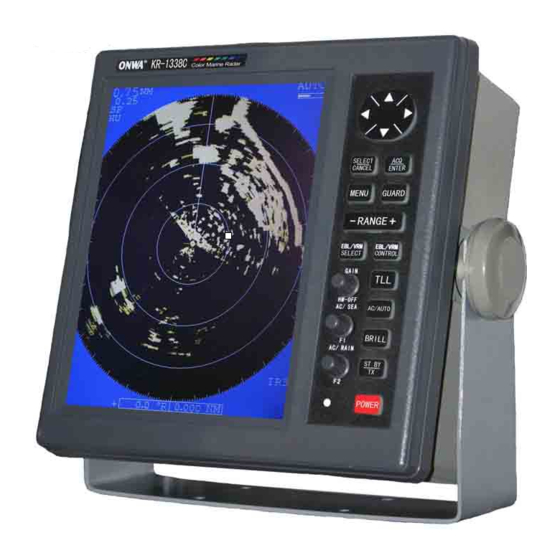
- Page 1 KR-1338C/1668C KR-1338C/1668C OPERATOR'S MANUAL 10.4 TFT LCD COLOR MARINE RADAR...
- Page 3 "DANGER","WARNING" and "CAUTION" notices throughout this manual. It is the responsibility of the operator and the installer of the equipment to read, understand and follows these notices. If you have any questions regarding these safety instructions, please contact a ONWA agent or dealer. WARNING Do not open the equipment.
- Page 4 CAUTION Use the proper fuse. Use of a wrong fuse can result in fire or permanent equipment damage. Do not use the equipment for other than its intended purpose. Personal injury can result if the equipment is used as a chair or stepping stool, for example. Do not objects on the top of the equipment.
-
Page 5: Table Of Contents
TABLE OF CONTENTS FOREWORD Features Model KR-1338C SPECIFICATION Model KR-1668C SPECIFICATION CONFIGERATION OF KR-1338C/1668C 1. PRINCIPLE OF OPERATION 1.1 What is Radar? 1.2 How Ships Determined Position Before Radar 1.3 How Radar Determines Range 1.4 How Radar Determines Bearing 1.5 Radar Wave Speed and Antenna Rotation Speed 1.6 The Radar Display... - Page 6 2.14 Measuring the Bearing 2.15 Using the Offset EBL 2.16 Shifting (off centering) the Pcture 2.17 Zoom 3. MENU OPERATION 3.1 Basic Menu Operation 3.2 Selecting the Presentation Mode 3.3 Magnifying Long Range Echoes (echo stretch) 3.4 Echo Trail 3.5 Suppressing Radar Interference 3.6 Selecting Pulsewidth 3.7 Guard Alarm 3.8 Watchman...
- Page 7 5.5 Life Expectancy of Magnetron 6. INSTALLATION 6.1 Antenna Unit Installation Sitting handling considerations 6.2 Display Unit Installation Mounting considerations 6.3 Exchange of Fuse for 24/32V Power Supply 6.4 Checking the Installation 6.5 Adjustments MENU TREE KR-1338C/1668C OUTSIDE DRAWING KR-1338C/1668C INTERCONNECTION...
-
Page 9: Foreword
While this unit can be installed by the purchaser, any purchaser who has doubts about his or her technical abilities may wish to have the unit installed by a ONWA representative or other qualified techician. The importance of a through installation can not be overemphasized. -
Page 10: Model Kr-1338C Specification
KR-1338C SPECIFICATION ANTENNA UNIT 1. Radiator : Slotted waveguide array 2. Radiator length : 55 cm 3. Horizontal beamwidth : 4 4. Vertical beamwidth : 25 5. Sidelobe : Within 20 off mainlobe; less than -18 dB Outside 20 off mainlobe; less than -23 dB 6. - Page 11 DISPLAY UNIT 1. Indication system : LCD digital display 2. Display : 10.4 LED backlight, 32-bit TFT Color LCD Display 3. Range scale (nm) : Range, Range interval and no. of Rings: 0.125(0.0625,2), 0.25(0.125,4), 0.75(0.25,3), 1(0.25,4), 1.5(0.5,3), 2(0.5,4), 3(1,3), 4(1,4), 6(2,3), 8(2,4), 12(3,4), 16(4,4), 24(6,4), 36(12,3) 4.
-
Page 12: Model Kr-1668C Specification
0.3 S, 1200 Hz (1.5, 2, 3nm) 0.8 S, 600 Hz (3, 4, 6, 8, 12, 16, 24, 36, 48, 64nm) 4. Bandwidth : Tx pulselength 0.3 S and 0.08 S : 25MHz Tx pulselength 0.8 S : 5 MHz 5. Other : See KR-1338C... - Page 13 DISPLAY UNIT 1. Range scale (nm): Range, Range interval and no. of Rings: 0.125(0.0625,2), 0.25(0.125,4), 0.75(0.25,3), 1(0.25,4), 1.5(0.5,3), 2(0.5,4), 3(1,3), 4(1,4), 6(2,3), 8(2,4), 12(3,4), 16(4,4), 24(6,4), 36(12,3), 48(12,4), 64(16,4) 2. Compass safe distance: Standard Compass Steering Compass Display unit 0.75m 0.6m Antenna unit 1.0m...
- Page 14 INTERFACE IEC 1162(NMEA0183) (Input) Own ship`s position: GGA>RMA>RMC>GLL Speed: RMA>RMC>VIG>VHW Heading (True): HDT>HDG*>HDT*>VHW>VHW* Course (True): RMA>RMC>VTG Course (Magnetic): VTG>RMA*>RMC Waypoint (Range, Bearing): RMB>BWC>BWR Loran time difference: RMA>GLC>GTD Water depth: DPT>DBT Water temperature: MDA>MTW XTE: RMB>XTE>APB *: Calculated value based Magnetic variation. AIS: VDO>VDM>ACA>ACS>ALR>ACK...
-
Page 15: Configeration Of Kr-1338C/1668C
CONFIGERATION OF KR-1338C/1668C ANTENNA UNIT KR-1338C KR-1668C Antenna cable KRC-003-10/15/20 10/15/20m Display UNIT 8 Pin 10.5 to 40VDC... -
Page 16: Principle Of Operation
1. PRINCIPLE OF OPERATION 1.1 What is Radar? The term "RADAR" is an acronym meaning "RAdio Detection And Ranging". Although the basic principles of radar were developed during World War II, echoes as an aid to navigation is not a new development. 1.2 How Ships Determined Position Before Radar Before the invention of radar, when running in fog near a rugged shoreline, ships would sound a short blast on their whistles, fire a shot, or strike a bell. -
Page 17: The Radar Display
1.6 The Radar Display The range and bearing of a target is displayed on what is called a Plan Position Indicator (PPI). This display is essentially a polar diagram, with the transmitting ship's position at the center. Images of target echoes are received and displayed at their relative bearings, and at their distance from the PPI center. -
Page 18: Basic Operation
2. BASIC OPERATION 2.1 Control Description Omnipad Brief press: Shifts cursor, VRM and EBL; Displays the data of target select items and options on selected with the cursor menu. Long press: (1) Acquires the target selected Terminates plotting of the target with the ominipad. -
Page 19: Display Indication And Markes
2.2 Display Indication and Markers Echo trail elapsed time Tuning indicator Heading (requires heading data) Heading line Echo trail time Guard zone Zoom AUTO TRAIL HDG 234.5 Echo Stretch .125NM 25:38 Range G OUT Range ring interval .0625 ZOOM Pulselength Off center OFFCENTER Display mode... -
Page 20: Turning The Radar On And Off
2.3 Turning the Radar On/Off Press the [POWER] key to turn the radar on or off. The control panel lights and a timer displays the time remaining for warm up of the magnetron (the device which produces radar pulses), counting down from 1:30 to 0:01. -
Page 21: Selecting The Range
SPEED TRIP Time-to-go to Stand-by ST-BY Speed 10.5 000.3nm DEPTH TEMPERATURE Depth Trip distance since power on +17.3 To Waypoint bearing heading Heading 092.5 Course CRS 180.0 M Time-to-go to WPT TTG 01:08 TO Waypoint 45.0 12.0NM Bearing TO Waypoint OWN SHIP 30 00 . -
Page 22: Setup Display Color
2.8 Setup display color In order to adapt to the different environments, the radar echo display the back- ground color and echo color can be set by users themselves, there are five kinds of background colors and three kinds of echo colors available. Setting methods are as follows: 1.By menu 1) Press [MENU] key open main menu;... -
Page 23: Adjusting Receiver Sensitivity
2.9 Adjusting Receiver Sensitivity The [GAIN] control adjusts the sensitivity of the receiver. It works in precisely the same manner as the volume control of a broadcast receiver, amplifying the signals received. The proper setting is such that the background noise is just visible on the screen. - Page 24 Adjusting the A/C SEA control The proper setting of the A/C SEA should be such that the clutter is broken up into small dots, and small targets become distinguishable. If the control is set Too low, targets will be hidden in the clutter, while if it is set too high, both sea clutter and targets will disappear from the display.
-
Page 25: Apply The A/C Rain (Reducing Rain Clutter)
2.11 Apply the A/C RAIN (reducing rain clutter) The vertical beamwidth of the antenna is designed to see surface targets even when the ship is rolling. However, by this design the unit will also detect rain clutter (rain, snow, hail, etc.) in the same manner as normal targets. Figure 2-4 Shows the appearance of rain clutter on the Display. -
Page 26: Measuring The Range
Heading Line North mark Figure 2-6 Heading line and north mark 2.13 Measuring the Range You can measure the range to a target three ways: by the range rings, by the cursor, and by the VRM (Variable Range Marker). By range ring Count the number of rings between the center of the display and the target. -
Page 27: Measuring The Bearing
To erase the VRM, press and hold down the [EBL/VRM CONTROL] key about two seconds. Range 6.0 NM Range ring Interval VRM1 Target Cursor VRM2 VRM1 Range 4.0 NM Cursor range 4.0 NM 3.0 NM VRM2 Range Figure 2-8 Measuring range by the cursor, range rings and VRM Note: You can display the range readout of the VRM and cursor in nautical miles, statute miles or kilometers. -
Page 28: Using The Offset Ebl
Target Cursor EBL1 EBL2 Cursor Bearing EBL1 bearing 40.0 R 40.0 R 4.0 NM EBL1 bearing 135.0 R Figure 2-9 How to measure bearing by EBL and cursor Note: The bearing readout for the EBL and the cursor can be display in relative or true bearing (true bearing requires heading sensor input) For north up and curse up display modes the bearing reference is always true. - Page 29 6.0 NM EBL1 origin (Initial position VRM1 of target) Target moved Here. Offset EBL (EBL1) VRM1 EBL1 70.0 R 6.0 NM VRM1 bearing range Figure 2-10 Predicting collision course by using the offset EBL Measuring range and bearing between two targets The procedure which follows shows how to measure the range and bearing between target "A"...
-
Page 30: Shifting (Off Centering) The Pcture
2.16 Shifting (off centering) the Picture Your vessel's position can be shifted up to 75% (not available on 48nm range) of the range in use to view the situation around your vesse l without changing the range or size of targets. 1. - Page 31 Cursor Cursor Place cursor Press [ZOOM] Where desired key to zoom Figure 2-13 Zoom Function Note1: Zoom is cancelled when range or presentation mode is changed. Cancelling Zoom Press the [F1 (A/C SEA)] control again.
-
Page 32: Menu Operation
3. MENU OPERATION 3.1 Basic Menu Operation The menu mostly contains less-often used functions which once preset do not require regular adjustment. To open or close the menu, press the [MENU] key. You can select items on the menu with the omnipad. The complete menu appears on page AP-1. -
Page 33: Magnifying Long Range Echoes (Echo Stretch)
2. Operate the omnipad to select "MODE". 3. Press the [ACQ/ENTER] key. With heading sensor connection the display and the display and the display mode indication at the top lefthand corner of the display change in the sequence of HU (heading up), CU (course up), NU (north up) and TM (true motion)when the [ACQ/ENTER] key is pressed. -
Page 34: Echo Trail
Bearing Bearing direction direction Range direction Echo stretch 1 Echo stretch 2 Figure 3-3 Echo stretch Note: This function magnifies not only targets but also sea clutter and radar interference. For this reason be sure the controls for adjustment of sea clutter and radar interference are properly adjusted before activating the echo stretch. -
Page 35: Suppressing Radar Interference
Fixed time trail 1. When the elapsed time clock counts up to the trail time selected, the elapsed time display freezes. 2. The oldest portions of trails are erased so only the latest trail, equal in length to the trail time selected, is shown. 3. -
Page 36: Selecting Pulsewidth
Figure 3-6 Radar interference Four levels of interference are available, including off; IR1,IR2,IR3 and OFF,IR3 provides the highest level of rejection. 1. Press the [MENU] key. 2. Select "OTHER MENU"and press the [ACQ/ENTER] key. 3. Select "6. Int Reject". 4. Select level desired by operation the omnipad. 5. -
Page 37: Guard Alarm
3.7 Guard Alarm The guard alarm allows the operator to set the desired range and bearing for a guard zone. When ships, islands, landmasses, etc. Violate the guard zone an audible alarm sounds and the offending target brinks to call the operator 's attention. - Page 38 Asterisk blinking Guard zone to set Drag cursor here. Drag cursor to top left corner of Mentally create the zone and press [GUARD]. guard zone to set. Guard zone Guard zone completed. Drag cursor to bottom right corner of zone and press [GUARD].
-
Page 39: Watchman
3.8 Watchman The watchman function periodically transmits the radar for minute to check for targets in a guard zone. If it finds change in the zone from the previous transmission it sounds the radar continuously. This feature is useful when you do not need the radar's function continuously but want to be alerted to radar targets in a specific area. -
Page 40: Display Navigation Data
3.9 Displaying Navigation Data Navigation data can be displayed at the screen bottom if this radar receives navi- gation input in IEC 1162 format. Navigation data include. position in latitude and longitude or Loran-C time difference range, bearing and time-to-go to both waypoint selected on the navigator and the cursor. -
Page 41: Other Menu Description
3.10 OTHER MENU Description Table 3-2 OTHER MENU Description Item Description 1.Panel Dimmer Select level of panel backlight. 2.Mark Brill Select brilliance of VRM, EBL, cursor, guard zone and WP marks. 3. HD Mark Select brilliance of heading mark. 4. Characters Select brilliance of characters. -
Page 42: Function Keys
3.11 Function Keys The function keys(F1 and F2) work like the auto-dialing feature of a teleph- one, automatically executing the function assigned to them. The function can be turned off by pressing appropriate function key again. Default settings F1: Background Color F2: Echo Color How to register menu items 1. -
Page 43: Suppressing Noise
3.12 Suppressing Noise " " Electrical noise can be suppressed by turning on 8.NOISE REJ on the OTHERS menu. 3.13 Adjusting Brilliance of Markers " " 2. Mark brill on the OTHER menu adjusts the brilliance of markers such as the cursor. -
Page 44: False Echoes
4. FALSE ECHOES Occasionally false echoes appear on the screen at positions where there is no target. In some cases the effects can be reduced or eliminated. The operator should familiarize himself or herself with the appearance and effects of these false echoes, so as not to confuse them with echoes from legitimate contacts. -
Page 45: Indirect Echoes
True echo Main-lobe Side-lobe Sprious target Antenna Figure 4-2 Side-lobe echoes 4.3 Indirect Echoes Heading Direct path Iine Target Indirect path Obstruction (mast,funnel Antenna etc.). True Target Indirect Indirect echo path Direct echo path Heading Iine ship True echo Bridge Indirect Indirect echo... -
Page 46: Blind And Shadow Sectors
Indirect echoes may be returned from either a passing ship or returned from a reflecting surface on your own ship, for example, a stack. In both cases, the echo will return from a legitimate contact to the antenna by the same indirect path. -
Page 47: Maintenance & Troubleshooting
Check for wear. Permanent damage If a crack is found it should be Radome cover to the antenna's internal circuitry temporarily repaired by using a (KR-1338C) will result if water leaks into the samll amount of sealing compound or adhesive. You should then radome. -
Page 48: Preventative Maintenance
5.1 Preventative Maintenance Regular maintenance is important for good performance. Always keep the equipment as free as possible from dirt, dust, and water splashes. Make sure all screws securing the components are properly tightened. A maintenance program should be established and should at least include the items listed in table 5-1. - Page 49 If... But... Then... you pressed the the control panel does try adjusting the control panel [POWER] key to not light backlighting on the OTHERS menu. turn on the radar battery may have discharged. check fuse in power cable. nothing appears on the try adjusting the brilliance.
-
Page 50: Life Expectancy Of Magnetron
5.5 Life Expectancy of Magnetron The following table shows the life expectancy of the magnetron. Life expectancy Model Type Code no. MSF1421B KR-1338C 2 000 - 3,000 hours V801 (Including stand-by) MAF1421B KR-1668C MAF1421B Table 5-3 Life expectancy of magnetron... -
Page 51: Installation
Also avoid running the cable in parallel with power cables. The compass safe distance should be observed to prevent deviation of the magnetic compass. Model Standard compass Steering compass KR-1338C 0.9m 0.7m... - Page 52 Do not paint the radome (Model KR-1338C) or to ensure proper emission of the radar waves. When this radar is to be installed on larger vessels, consider the following points: (1) The signal cable run between the antenna and the display comes in lengths of 10 m, 15 m, 20 m and 30 m.
- Page 53 Mounting platform Holes for antenna unit: The mounting surface must be parallel with the waterline and provided with four holes whose dimensions are shown in the outline drawing attached at the end of this manual. The unit is adjusted so a target echo returned from the bow direction will be shown on the zero degree (heading line) position on the screen.
- Page 54 Wiring and final preparation Drill a hole of at least 20 millimeters diameter through the deck or bulkhead to run the signal cable between the antenna unit and display unit. (To prevent electrical interference avoid running the signal cable near other electrical equipment and in parallel with power cables.) Pass the cable through the hole.
- Page 55 Fix the shield cover. Do not pinch the cable. Loosely fasten the radome fixing bolts. You will tighten them after confirming magnetron heater voltage. Mounting(KR-1668C) Figure 6-5 Typical antenna unit mounting locations 1. Drill four fixing bolt holes (13 millimeters dia.), One cable entry hole (approx. 50 millimeters dia.) In the mounting platform.
- Page 56 Note: Tighten the bolts by their nuts to prevent damage to the seal washer. Do not turn the bolts to secure the antenna housing. Figure 6-7 How to mount the antenna housing Connections Only the signal cable runs from the display unit to the antenna unit. Make the hole for passing the cable through the bulkhead or deck at least 20 millimeters diameter.
- Page 57 4. Fasten the cable gland assembly. 5. Connect the lead wires to CON-0906 in the antenna housing by referring to the Interconnection Diagram. Fasten the ground washer at the bottom of the antenna housing as shown in Figure 6-9. CON-0906 Figure 6-9 Connection in the antenna housing Final preparation 1.
- Page 58 Apply grease to the O-ring and set it to the center of the radiator bracket. Coat the radiator fixing bolts with silicone sealant. Fasten the radiator to the radiator bracket with the ONWA logo on the radiator facing ship`s bow. RA12 Figure 6-12 Fastening the radiator to the radiator bracket 4.
-
Page 59: Display Unit Installation Mounting Considerations
6. Fasten the ground wire (black) of the signal cable to the chassis as shown in Figure 6-13. 7. Loosely fasten the antenna housing cover. You will tighten the fixing bolts after confirming magnetron heater voltage. 6.2 Display Unit Installation Mounting considerations When selecting a mounting location for the display unit keep in mind the following points. - Page 60 Connections Connect the power cable to the power cable connector on the rear of the display unit. Connect the signal cable to connector on the rear of the display unit. Run a ground wire (local supply) between the ground terminal on the rear of the display unit and the ship's superstructure.
- Page 61 2. NMEA2 (8 pins connector) 1.+12V 2.NMEA2 Input+ 3.NMEA2 Input 4.GND 5.+12V 6.NMEA3 Input+ 7.NMEA3 Input Option Power Fuse Holder Upgrade NMEA-1 Connector NMEA-2 Connector Figure 6-14 Display connect CAUTION CAUTION Ground the equipment. Replace ther fuses to 5A for Ungrounded equipment might 24/32VDC operation emit or receive electromagnetic...
-
Page 62: Exchange Of Fuse For 24/32V Power Supply
6.3 Exchange of Fuse for 24/32V Power Supply The power cable comes with a 10A fuse in the fuse holder. This fuse is for use with a 12V DC power supply. For 24V/32V DC power supply, replace the fuse with the 5A fuse (supplied) to fuse holder. 6.4 Checking the Installation After completing the installation, it is a good idea to recheck it to be sure all steps were correctly done. - Page 63 [ Installation Setup] Select item by omnipad and ress ENTER key. . Nav Talker 2. Depth Unit 3. Temp Unit 4. Hdg Sensor Magnet Gyro 5. Key Beep 6. Ant on Tx Rotate Stop 7. Dead Sector ~180 8. Tuned/Video Auto Adjustment 9.
- Page 64 Entering antenna height The STC curve changes with respect to antenna height above the waterline. Enter antenna height above the waterline to optimize the STC curve. 1. Select "12.Antenna Height" on the installation setup menu and press the [ACQ/ ENTER] key. 2.
- Page 65 Adjusting sweep timing(Adjustment range:0.000~4.266nm) This adjustment ensures proper radar performance, especially on short ranges. The radar measures the time required for a transmitted echo appears on the display based on this time. Thus, at the instant the transmitter is fired, the sweep should start from the center of the display (sometimes called sweep origin.) A trigger pulse generated in the display unit goes to the antenna unit through the signal cable to trigger the transmitter (magnetron).
- Page 66 Adjusting MBS (Main Ban Suppression)(Adjustment: 0.00~0.25) Main bang (black hole), which appears at the display center on short ranges, can be suppressed as follows. 1. Transmit on long range about 10 minutes. 2. Adjust the gain to show a small amount of noise on the display. 3.
- Page 67 1. Turn on the radar(if it is not already on) and set it in stand-by. 2. Open the antenna housing (radome) cover. Connect a multitester, set to 10V DC range. Model Check point Rating Adjustment Point KR-1338C Tp803 #4,#6 7.4~7.6V V 801 on MD Borad Tp803 #4,#6 7.4~7.6V...
-
Page 68: Menu Tree
MENU TREE MENU KEY RINGS(Off,1,2,3,max) EBL OFFSET Off On SHIFT Off On ZOOM Off On MODE HU CU NU TM DISP DATA ECHO TRAIL Off On ECHO STRTCH Off ES 1 ES2 .Display MENU .Simulation OTHER MENU .AIS Ship listing .Vector Length .Panel Dimmer 1,2,3,4... -
Page 69: Ais
How AIS Works Automatic Identification System (AIS) is a reporting system used in the identification of marine vessels and its location. Vessels equipped with this system allows each other to communicate automatically, dynamically and regularly update their position, speed, course and information such as vessel identity. - Page 70 2. Select [ AIS MENU ] & press [ ACQ/ENTER ] key, Select 1.Display , press [ ] or [ ] key select & p ress [ MENU] k ey t o r eturn. N ow if AIS word appears on the upper screen of the display , The AIS symbol is shown in the radar echo area.
- Page 71 How to check the information received from Ships with AIS ? In the AIS menu, select 3. AIS Ship Listing and press [ACQ/ENTER]. The AIS tabulation will appear and demonstrate the other ships basic information. Figure 3 AIS Ship Listing How to determine the target ships detailed information There are two methods by which we can view a ships sailing detailed information:...
- Page 72 2.By cursor When the cursor is moved to the target ship and press [ENTER] key, selected ship will appear as shown in Figure 4 and the AIS data shall appear as shown in Figure 5. Note: If the display setting of the radar screen is at mode , it will briefly display the AIS information as shown in Figure 6.
- Page 73 How to view your ships AIS information? Press AIS menu, select 11. Own Ship Data then AIS detailed information will appear as shown in Figure 7. Figure 7 Own Ship data Setting vector length of time This function is used to set your ship and target ships vector length. The mark represents the vector in accordance with the present voyage.
- Page 74 Past Position Display The past position display shows equally time-spaced dots marking past positions of activated AIS targets. A new dot is added at preset time intervals until the preset number is reached. If a target changes its speed, the spacing will be uneven.
- Page 75 AIS Collision Alarm (CPA, TCPA) The AIS continuously monitors the predicted range at the Closest Point of Approach (CPA) and predicted time to CPA (TCPA) of each AIS target. When the predicted CPA of an AIS target becomes smaller than a preset CPA range and its predicted TCPA less than a preset TCPA limit, the audio alarm sounds and the symbol of the offending AIS target becomes red, bold 2 times and flashes together with its vector.
- Page 76 In/Out harbour This function is used to avoid ships in the harbour because too many AIS boats nearby may cause continuous alarm. Upon entering the port you may select "ON" , CPA and TCPA alarm will be disabled. Setting IN/OUT harbour Enter AIS menu, select 9.
- Page 77 Prompted of data processing The radar system can access a variety of NMEA data, including AIS / GPS, direction and water depth data. At boot time, if not turned on AIS, the radar will appear on-screen prompts such as: "No AIS device." To know there are many, such as "AIS signal loss"...
- Page 78 AIS ship symbol status description SYMBOL STAT US REMARKS An isosceles, acute-angled triangle should be used with its centroid representing the target's reference position. The most acute apex of the triangle should Sleeping target be aligned with the heading of the target, or with its COG, if heading information is not available.
-
Page 79: Kr-1338C/1668C Outside Drawing
130.5 276.8 27.5 276.8 TYPE KRD-1003 KR-1338C NAME DISPLAY UNIT KR-1668C... - Page 80 ONWA ONWA Antenna base plate Packing Effective Radome thread length 5 -10 mm Flat washer Platform Spring washer Hex bolt Apply silicone sealant MODE KRA-1002 KR-1338C NAME SCANNER UNIT...
- Page 81 KR-1338C/1668C INTERCONNECTION 1250 RA12 RADIATOR S=1/25 RA12: KR-1668C FORWARO RA12 M12 BOLT SEAL WASHER CW10530X PLATFORM F.W . M12 NUT CENTER OF ROTSTION 4-M4 10 FIXING HOLES CABLE ENTRY CLAM PLATE MOUNTING DIMEENSIONS RUBBER PACKING MODE KRA-2002 KR-1668C NAME SCANNER UNIT...
- Page 83 BL-12V LCD DATA BUS MOTOR(+) MOTOR(-) +12V -12V SHIP`S MAINS + SHIP`S MAINS + SHIP`S MAINS - SHIP`S MAINS + SHIP`S MAINS - SHIP`S MAINS -...
- Page 85 SHIP`S MAINS + 12/24/32VDC SHIP`S MAINS - KRC-003-10/15/20 +12V +12V -12V -12V TX TRIG NMEA-1 P/L A P/L B +3.3V GPS IN NMEA OUT1 NAV/HEADING/DEPTH DAT A (NMEA0183) BEARING MOTOR (+) HEADING MOTOR (-) NMEA-2 ECHO & GYRO +3.3V GYRO IN NMEA OUT2 HEADING/DEPTH DATA ECHO IN...
Need help?
Do you have a question about the KR-1338C and is the answer not in the manual?
Questions and answers