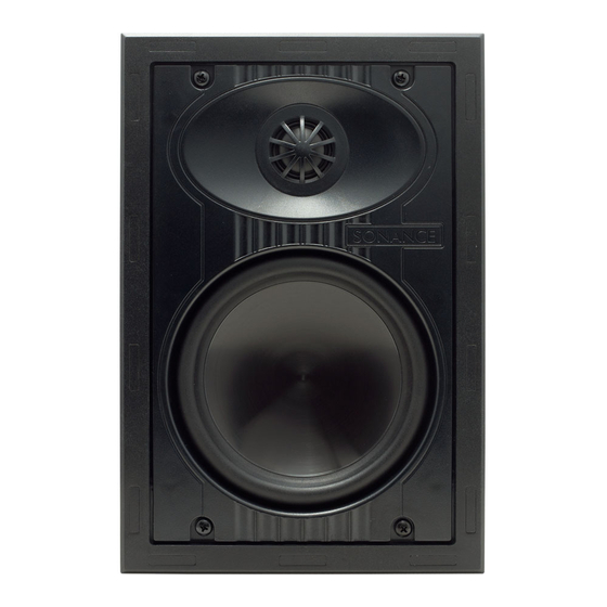
Sonance VP65 XT Instruction Manual
Visual performance series extreme speakers
Hide thumbs
Also See for VP65 XT:
- Brochure (12 pages) ,
- Specifications (2 pages) ,
- Specifications (4 pages)
Advertisement
Quick Links
I N S T R U C T I O N M A N U A L
V I S U A L P E R F O R M A N C E
E X T R E M E
Introduction
Thank you for purchasing Sonance Visual Performance Series
Extreme Speakers. These weatherproof 6" speakers can provide
superior sound quality for high-humidity areas and are built to
survive temperature extremes from –30°F – +175°F (–34°C
+79°C). Their shallow depth makes them easy to install in a vari-
ety of challenging spaces. Visual Performance Extreme speakers
provide excellent sound in yachts, saunas, steam rooms, and hot
tub areas.
This manual covers the following speaker models: VP65 XT
(rectangular), VP65R XT (round), VP65S XT (square), VP65R SST
XT (round, Single-Stereo Technology
S
W
:
A F E T Y
A R N I N G
T
F
HESE
SPEAKERS
HAVE
AST
SPEAKER FROM FALLING OUT OF THE MOUNTING HOLE DURING THE
.
INSTALLATION PROCESS
T
F
H E E D G E S O F T H E
A S T
U
S E C A U T I O N W H E N H A N D L I N G T H E S P E A K E R
Box Contents
Sonance VP65 XT, VP65R XT, and VP65S XT speaker boxes contain
(2) speakers, (2) paint plugs (installed on the fronts of the
speakers), (2) paintable grilles and (1) mounting cutout
template.
Sonance VP65R SST XT speaker boxes contain (1) speaker,
(1) plastic paint plug (installed on the front of the speaker),
(1) paintable grille and (1) mounting cutout template.
Speaker Placement
S t e r e o S p e a ke r P l a c e m e n t ( V P 6 5 X T )
• Place the left and right speakers on the same wall, from 6 to
10 feet (1.8 – 3m) apart.
• If the listeners will be seated the speakers should be located
38 – 42 (97 – 107cm) inches from the floor.
• If listeners will be standing the speakers should be located
5 feet (1.5m) from the floor.
• The ideal listening distance will be between 4 and 10 feet (1.2
and 3m) away from the speakers. The best stereo performance
will be midway between the speakers.
Use Figure 1 (next column) as a guide
D i s t r i b u t e d A u d i o P l a c e m e n t
( V P 6 5 R X T / V P 6 5 S X T / V P 6 5 R S S T X T )
Sonance VP65R XT, VP 65S XT and VP65R SST XT in-ceiling
speaker models provide excellent coverage in distributed
audio systems from a wide variety of installation locations.
The table and illustration in Figure 2 show how far apart
®
S E R I E S
S P E A K E R S
®
).
M
®
OUNT
TABS
THAT
PREVENT
M
O U N T TA B S A R E V E R Y S H A R P
.
–
(Standing Listeners)
38" – 42"
(97cm – 107cm)
(Seated Listeners)
F
IGURE
THE
speakers can be placed at various ceiling heights while still
providing good coverage for all listeners.
.
The VP65R SST XT reproduces both stereo channels from a single
location, making it ideal for use in bathrooms, saunas, or in any
location where a pair of stereo speakers would be impractical.
C
OVERAGE
A
REA
S
P E A K E R
F O R A
8-F
C
OOT
EILING
10-F
C
OOT
EILING
12-F
C
OOT
EILING
14-F
C
OOT
EILING
F
2: D
IGURE
Before Installation: Retrofit
1. Determine the location for the speaker (see Speaker
Placement on page 1).
2. Perform an obstruction survey to be certain that there are
no studs, conduit, pipes, heating ducts, pocket doors or
air returns in the wall cavity that will interfere with the
speaker.
6' – 10' (1.8m – 3m)
Apart
5' (1.5m)
1: S
S
P
TEREO
PEAKER
LACEMENT
S
PEAKER
S
PACING
C
OVERAGE
A
REA
S
(
P AC I N G
I N F E E T
D
A
S
I S T R IB U T E D
U DI O
YS T EM
S
L
S
TANDING
ISTENER
EATED
5.7' (1.7m) Apart
9.5' (2.9m) Apart
9.7' (3.0m) Apart
13.5' (4.1m) Apart
13.7' (4.2m) Apart
17.5' (5.3m) Apart
17.7' (5.4m) Apart
21.5' (6.6m) Apart
A
S
ISTRIBUTED
UDIO
PEAKER
)
L
ISTENER
S
PACING
1
Advertisement

Summary of Contents for Sonance VP65 XT
-
Page 1: Box Contents
Box Contents PEAKER Sonance VP65 XT, VP65R XT, and VP65S XT speaker boxes contain PACING (2) speakers, (2) paint plugs (installed on the fronts of the speakers), (2) paintable grilles and (1) mounting cutout template. - Page 2 (see Figure 3). Connection Terminals (1 Set on VP65R XT, VP65S XT, VP65 XT; 2 Sets on VP65R SST XT) FastMount...


Need help?
Do you have a question about the VP65 XT and is the answer not in the manual?
Questions and answers