Table of Contents
Advertisement
Available languages
Available languages
Quick Links
Advertisement
Table of Contents

Related Manuals for JVC DT-V17G15


Summary of Contents for JVC DT-V17G15
- Page 1 MULTI FORMAT LCD MONITOR DT-V17G15 INSTRUCTIONS This is the English instruction manual. Instruction manuals in other languages (German, French, Italian, Spanish, Russian, Chinese) are included on the supplied CD-ROM as PDF files. LCT2699-001A...
-
Page 2: Important Safeguards
Safety Precautions (English) The lightning flash with arrowhead symbol, within an equilateral triangle is CAUTION intended to alert the user to the presence of uninsulated “dangerous voltage” RISK OF ELECTRICAL SHOCK within the product’s enclosure that may DO NOT OPEN be of sufficient magnitude to constitute a risk of electric shock to persons. - Page 3 Do not attempt to service this product yourself, as opening or • The AC power supply is controlled by turning on/off the removing covers may expose you to dangerous voltages and POWER switch on the rear panel. If the product is installed in a other hazards.
-
Page 4: Dear Customer
If you wish to dispose of this product, please visit our web page http:// contain noise. In such cases, please keep the cable away from the www.jvc.eu/ to obtain information about the take-back of the product. sources of the disturbance. -
Page 5: Sicherheitsmaßregeln (Deutsch)
Sicherheitsmaßregeln (Deutsch) The lightning flash with arrowhead symbol, within an equilateral triangle is CAUTION intended to alert the user to the presence of uninsulated “dangerous voltage” RISK OF ELECTRICAL SHOCK within the product’s enclosure that may DO NOT OPEN be of sufficient magnitude to constitute a risk of electric shock to persons. - Page 6 Sicherheitsmaßregeln (Deutsch) (Forts.) Versuchen Sie nicht, das Produkt selber zu warten, wie etwa • Die Netzstromversorgung wird durch Ein-/Ausschalten des durch Öffnen von Abnehmen von Abdeckungen. Im Inneren Netzschalters (POWER) an der Rückseit gesteuert. Wenn befinden sich Teile mit gefährlicher Hochspannung und andere das Produkt an einem Ort aufgestellt ist, wo er sich nicht Gefahrenquellen.
- Page 7 Richtlinien. Dieses Gerät ist Sicherheit. für professionelle Videoausrüstungen ausgelegt und kann in den folgenden Umgebungen verwendet werden. Die europäische Vertretung von JVC KENWOOD Corporation ist: • Umgebung mit kontrollierter EMV (zum Beispiel speziell gebaute JVC Technical Services Europe GmbH Sende- oder Aufnahmestudios) und ländliche Umgebungen im...
-
Page 8: Précautions De Sécurité (Français)
Précautions de sécurité (Français) The lightning flash with arrowhead symbol, within an equilateral triangle is CAUTION intended to alert the user to the presence of uninsulated “dangerous voltage” RISK OF ELECTRICAL SHOCK within the product’s enclosure that may DO NOT OPEN be of sufficient magnitude to constitute a risk of electric shock to persons. - Page 9 N’essayez pas de réparer vous même cet appareil, car ouvrir • L’alimentation secteur est commandée par la mise sous/hors ou retirer des couvercles vous exposerait à des tensions tension au niveau de l’interrupteur POWER sur le panneau dangereuses ou d’autres dangers. Confier toutes les réparations arrière.
- Page 10 Ce matériel électrique. est conçu pour des applications vidéo professionnelles et peut être utilisé dans les milieux suivants: Le représentant européen de JVC KENWOOD Corporation est: • Milieux contrôlés EMC (par exemple studio d’enregistrement ou JVC Technical Services Europe GmbH conçu pour la diffusion), et en extérieur (loin des lignes de chemins...
-
Page 11: Precauzioni Di Sicurezza (Italiano)
Precauzioni di sicurezza (Italiano) The lightning flash with arrowhead symbol, within an equilateral triangle is CAUTION intended to alert the user to the presence of uninsulated “dangerous voltage” RISK OF ELECTRICAL SHOCK within the product’s enclosure that may DO NOT OPEN be of sufficient magnitude to constitute a risk of electric shock to persons. - Page 12 Precauzioni di sicurezza (Italiano) (cont.) Non tentare di riparare l’apparecchio da sé, poiché l’apertura o • L’alimentazione CA dell’apparecchio è controllabile agendo la rimozione dei coperchi può esporre a tensioni pericolose o ad sull’interruttore POWER del pannello posteriore. Se altri pericoli. Si raccomanda piuttosto di rivolgersi a personale l’apparecchio è...
- Page 13 (Per gli utenti aziendali) Qualora si desideri smaltire questo prodotto, visitare la nostra pagina web http://www.jvc.eu/ per ottenere informazioni sul ritiro del prodotto. [Per altri Paesi al di fuori dell’Unione Europea] Qualora si desideri smaltire questo prodotto, effettuare lo smaltimento in conformità...
-
Page 14: Precauciones De Seguridad (Español)
Precauciones de seguridad (Español) The lightning flash with arrowhead symbol, within an equilateral triangle is CAUTION intended to alert the user to the presence of uninsulated “dangerous voltage” RISK OF ELECTRICAL SHOCK within the product’s enclosure that may DO NOT OPEN be of sufficient magnitude to constitute a risk of electric shock to persons. - Page 15 Jamás intente reparar este producto por su cuenta, ya que • La fuente de alimentación de CA se controla mediante la si abre o desmonta las cubiertas, puede quedar expuesto activación/desactivación del interruptor POWER en el panel a descargas de tensión y otros peligros. Deje todo el trasero.
- Page 16 Directivas Europeas. Este equipo ha sido diseñado para aparatos de vídeo profesional y puede utilizarse en los El representante para Europa de JVC KENWOOD Corporation es: siguientes entornos: JVC Technical Services Europe GmbH •...
- Page 17 Меры предосторожности (Русский) The lightning flash with arrowhead symbol, within an equilateral triangle is CAUTION intended to alert the user to the presence of uninsulated “dangerous voltage” RISK OF ELECTRICAL SHOCK within the product’s enclosure that may DO NOT OPEN be of sufficient magnitude to constitute a risk of electric shock to persons.
- Page 18 Меры предосторожности (Русский) (продолж.) • POWER, POWER, • : 120/220 – 240 , 50 • : 12 B – 17 B • • • • • • • • • • Крепежные отверстия стандарта VESA VESA M4 x 10 Крюк и винт (M4 x 10 мм) Крюк...
- Page 19 JVC KENWOOD Corporation: JVC Technical Services Europe GmbH Postfach 10 05 04 • EMC ( 61145 Friedberg Germany ( . .) 2,0 m (H05VV-F 3 × 0,75 2,0 m 1,5 m DVI ( 2,0 m RS-232C ( 2,0 m D-sub 9-...
- Page 20 • • • • • • • • AC 120 V AC 220 – 240 V AC 120 V AC 220 – 240 V AC 220 – 240 V • – – – • – – • • AC 120 V AC 220 –...
- Page 21 • POWER POWER • • 120 V/220 – 240 V 50 Hz/60 Hz • • 12 V – 17 V • • • • • • • • VESA M4 x 10 mm VESA M4 x 10 mm...
- Page 22 JVC KENWOOD Corporation • JVC Technical Services Europe GmbH Postfach 10 05 04 61145 Friedberg 2.0 m H05VV-F 3 x 0.75 mm 2.0 m 1.5 m 2.0 m RS-232C 2.0 m D-sub 9- RS-485 2.0 m REMOTE 2.0 m http://www.jvc.eu/...
-
Page 23: Table Of Contents
Operating Precautions The LCD panel and backlight have life expectancy. Due to the basic characteristics of the LCD panel, an afterimage or uneven display may occur. It is recommended that you change images occasionally, activate the power saving function, or often turn off the power to reduce the load on the LCD panel. - Page 24 Installation ● Do not rest your arm on the monitor or lean against the monitor. ● Do not touch the LCD panel when installing the monitor. ● Be sure to install the monitor securely to prevent the monitor from falling over, which may cause damage to the monitor or injury. ●...
- Page 25 ● To install the monitor on a shelf or any other suitable surface using screws You can install the monitor on a shelf etc. by changing the position of the bottom plate of the stand to a rearward position. CAUTION ●...
-
Page 26: Index Of Parts And Functions
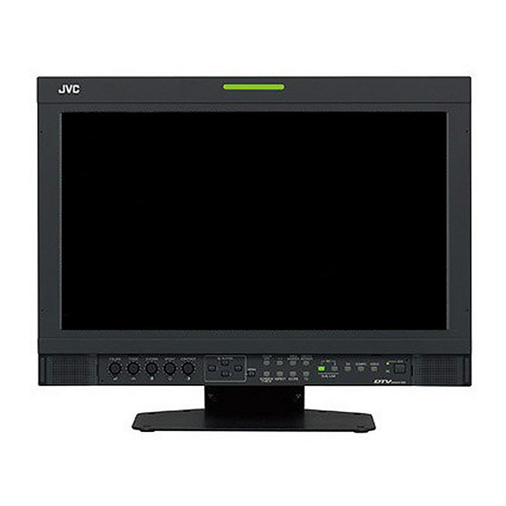
Index of Parts and Functions Front panel Tally lamp This lamp is controlled by the tally function of the MAKE/TRIGGER terminal. • You can select the color of the tally lamp from “GREEN” or “RED.” (☞ “TALLY SELECT” in “FUNCTION SETTING” on page 36 and “External Control” on page 40) •... -
Page 27: Menu Button
6 MENU button t INPUT SELECT buttons/lamps Activates/deactivates the display of the MAIN MENU Selects an input. (☞ “Menu Operations” on page 31). SDI 1: Input from the E. AUDIO SDI/HD SDI/ 7 COLOR OFF button/lamp SD SDI (IN 1) terminal SDI 2: Input from the E. -
Page 28: Rear Panel
Index of Parts and Functions (cont.) Rear panel Carry handle Use this handle when carrying the monitor. Security slot Attach a security wire to this slot. Note for connections • Before making any connections, turn off all the equipment. • Use a cord whose plugs correctly match the terminals on this monitor and the equipment. -
Page 29: Showing Input Signals
Showing Input Signals Audio Channel Selection Select audio channels emitted from the speakers (L/R) and the AUDIO (MONITOR OUT)(OUT1(L)/OUT2(R) terminals, when EMBEDDED AUDIO signals come in to the SDI terminal and SDI input is selected. ● You have to choose a group of selectable audio channels before the channel selection (☞ “E.AUDIO GROUP” in “AUDIO SETTING” on page 34). ●... -
Page 30: On The Status Display
Showing Input Signals (cont.) On the Status Display If you press the INPUT SELECT button (☞ t on page 27) currently lit, the status of the input signal and setting of MUTING are displayed for about 3 seconds. ● Make the setting to display/hide the status in “STATUS DISPLAY” of the “INFORMATION.” (☞ page 38) ●... -
Page 31: Setting The Menu
Setting the menu Menu Operations MAIN MENU SET-UP MENU Item being Display the menu. selected To display the MAIN MENU ➔ Press MENU button. Operation To display the SET-UP MENU guide ➔ Press button while holding button. Press buttons to select an item, then press button. MAIN MENU ●... -
Page 32: Main Menu
Setting the menu (cont.) MAIN MENU PICTURE FUNCTION Setting for the picture quality. Item Content Setting value APERTURE * Activates/deactivates the function at the level set in “APERTURE LEVEL.” OFF, ON APERTURE LEVEL * Simultaneously corrects the frequency characteristics of the RGB colors. 01 –... - Page 33 *1*2 MARKER Settings for marker functions. Item Content Setting value AREA MARKER * Activate/deactivate the area marker and select the style of it. The setting values and features are as follows. LINE HALF Deactivate the marker. HALF+L LINE Displays the area with an outline. BLK.
-
Page 34: Audio Setting
Setting the menu (cont.) AUDIO SETTING Settings for the audio output balance, EMBEDDED AUDIO signals and level meter. Item Content Setting value BALANCE Adjust the balance between the right and left speakers. L5 – L1, 0, R1 – R5 E.AUDIO GROUP * Select the audio channel group of the EMBEDDED AUDIO signals. - Page 35 SCOPE SETTING Configure the settings for the wave form monitor and vector scope. Item Content Setting value GAIN Adjust the input gain level. –10 – +10 SIZE * Set the window size. NORMAL, LARGE POSITION * Select the window position. 1 (Lower right), 2 (Lower left) 3 (Upper left), 4 (Upper right) TRANSPARENT...
-
Page 36: Function Setting
Setting the menu (cont.) SET-UP MENU FUNCTION SETTING Configure the sub menu display, the lighting color of the tally lamp, the brightness of the button lamps. Item Content Setting value sub menu POSI. “ ” LOWER1 Select the contents and displaying position of sub menu. - Page 37 PICTURE SUB ADJ. Configure the standard level of image adjustment. Item Content Setting value CONTRAST * Adjust the standard level for the contrast adjusted with the CONTRAST knob on the – 20 – +20 front panel. BRIGHT * Adjust the standard level for the brightness adjusted with the BRIGHT knob on the –...
- Page 38 Setting the menu (cont.) REMOTE SETTING (☞ “External Control” on pages 40) Settings for the external control. Item Content Setting value SERIAL TYPE Select the input terminal used for external control by serial RS232C communication. RS485 PARALLEL TYPE Select the external control method for the MAKE/TRIGGER terminal. MAKE, TRIGGER, SET ☞...
- Page 39 CONTROL LOCK Setting value: OFF, VOL.LOCK, ALL LOCK Settings for disabling the buttons on the front panel. ● The following operations are not available when “VOL.LOCK” is selected. – VOLUME adjustment knob – Picture adjustment knob ● The “ALL LOCK” function disables to control the buttons on the front panel. But following operations are available. –...
-
Page 40: External Control
External control About the external control Using the MAKE/TRIGGER This monitor has three external control terminals. system ● MAKE/TRIGGER terminal (RJ-45): The following external control The MAKE/TRIGGER terminal is configured as follows. systems are available. You can assign a function to each pin terminal in “REMOTE SETTING.” 1 MAKE (make contact) system: (☞... - Page 41 <Functions controlled by the MAKE/TRIGGER system> Display Functions to be controlled Opening Short-circuiting TALLY SEL Selects the color of the tally lamp Green SDI 1 Changes the input to “SDI 1” Invalid Valid SDI 2 Changes the input to “SDI 2” Invalid Valid Changes the input to “DVI”...
-
Page 42: Using The Serial Communication
External Control (cont.) Using the serial communication You can control the monitor from a personal computer etc. via the RS-485 or RS-232C terminal. ● Consult your dealer for the details of the external control specification. <Communication specifications> Terminal Input terminal Cable Communication specifications specification... - Page 43 <Basic command list> Commands Functions Data ! * ** B C N 1 Cr Starts communication (connection) No data ! * ** B C N 0 Cr Terminates communication (termination) No data ! * ** B I D S Assigns the control ID 01 –...
-
Page 44: Troubleshooting
Troubleshooting Solutions to common problems related to the monitor are described here. If none of the solutions presented here solve the problem, unplug the monitor and consult an authorized dealer or service center. Symptom Probable cause and corrective action Page ●... -
Page 45: Specifications
Self-check program This monitor has a self-check function, which allows it to detect malfunctions and alert you. This makes troubleshooting easier. Whenever a problem occurs, one or some of the INPUT SELECT (DVI, COMPO., VIDEO) lamps will flash. If this happens, follow the steps below and contact your dealer to resolve the problem. -
Page 46: Lcd Panel
Specifications (cont.) General Model name DT-V17G15 Type MULTI FORMAT LCD MONITOR Screen size Type 17 wide format Aspect ratio 16:9 ☞ “Available signals” on page 47 Compliant video signal format Format 3G SDI SMPTE424M/SMPTE425M DUAL LINK HD SDI SMPTE372M HD SDI... -
Page 47: Available Signals
Notice on transportation This monitor is precision equipment and needs dedicated packing material for transportation. Never use any packing material supplied from sources other than JVC or JVC-authorized dealers. ● For easy understanding, pictures and illustrations are emphasized, omitted or composed, and may be slightly different from actual products. - Page 48 Specifications (cont.) Computer signals (preset) DVI-D (HDCP) terminals Resolution Frequency Signal name Scan system Horizontal Vertical Horizontal (kHz) Vertical (Hz) VGA60 31.5 59.9 Non-interlace WVGA60 31.5 59.9 Non-interlace SVGA60 37.9 60.3 Non-interlace XGA60 1024 48.4 60.0 Non-interlace WXGA (1280) 1280 47.8 60.0 Non-interlace...
- Page 49 Краткое руководство пользователя Передняя панель Сигнальный индикатор Данный индикатор управляется функцией сигнальной индикации разъема MAKE/TRIGGER. • Вы можете выбрать цвет сигнального индикатора из “GREEN” или “RED”. • При нажатии кнопки, недоступной для текущего входа или формата сигнала, отображается “NO EFFECT” (индикатор горит даже если...
- Page 50 Краткое руководство пользователя (продолж.) 6 Кнопка MENU t Кнопки/индикаторы INPUT SELECT Включает/выключает отображение MAIN MENU. Выбор входа. 7 Кнопка/индикатор COLOR OFF SDI 1: Вход с разъема E. AUDIO SDI/HD SDI/ SD SDI (IN 1) Отображает только сигнал яркости. SDI 2: Вход...
- Page 51 Задняя панель Ручка для переноски Пользуйтесь этой ручкой при переноске монитора. Гнездо безопасности Прикрепите шнур безопасности к этому гнезду. Примечание по подключениям • Перед выполнением подключения выключите все устройства. • Используйте шнур, штепсельные разъемы которого точно совпадают с разъемами на мониторе и устройствах. •...
- Page 52 LCT2699-001A © 2012 JVC KENWOOD Corporation...
Need help?
Do you have a question about the DT-V17G15 and is the answer not in the manual?
Questions and answers