Table of Contents
Advertisement
Advertisement
Table of Contents

Related Manuals for Terbly LSP60

Summary of Contents for Terbly LSP60
- Page 1 LED MOVING HEAD USER MANUAL LSP60 KEEP THIS MANUAL FOR FUTURE NEEDS...
-
Page 2: Table Of Contents
Contents 1. Features ................................2 2. Overview................................. 3 3. SAFETY INSTRUCTIONS .......................... 3 3.1) Important safety warns........................3 3.2) GENERAL GUIDELINES ........................ 4 4. INSTALLATION INSTRUCTIONS......................5 4.1) Mounting the device ........................... 5 5. DMX-512 control connection........................9 6. DMX-512 connection with DMX terminator ....................9 7. -
Page 3: Features
Thank you for your patronage. We are confident that our excellent products and service can satisfy you. For your own safety, please read this user manual carefully before installing the device. In order to install , operate, and maintain the lighting safety and correctly. We suggest that the installation and operation should be done by the verified technician and follow the instruction strictly. -
Page 4: Overview
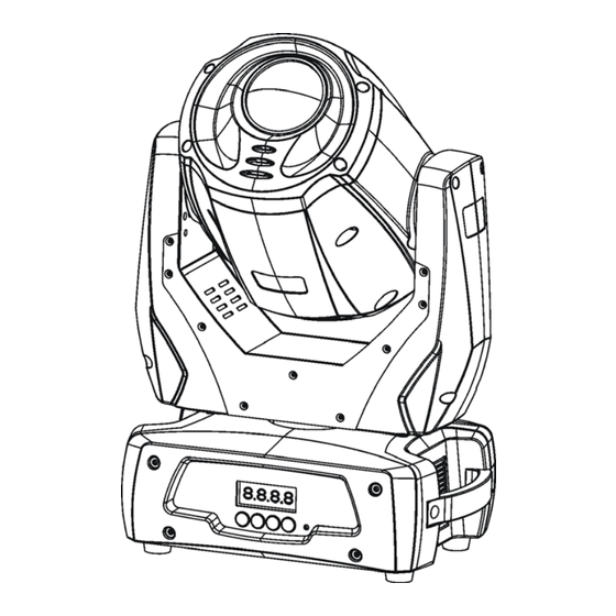
2. Overview 1) Lens 2) Display 3) Mode/Esc-button 4) Up-button 5) Down-button 6) Enter-button 7) Microphone 8) Handle 9) 3 pin-DMX out 10) 3 pin-DMX in 11) 5 pin-DMX out 12) 5 pin-DMX in 13) Power switch 14) Fuse 15) Power supply 3. -
Page 5: General Guidelines
This device falls under protection-class I. Therefore it is essential that the device be earthed. The electric connection must carry out by qualified person. Make sure that the available voltage is not higher than stated at the end of this manual. Make sure the power cord is never crimped or damaged by sharp edges. -
Page 6: Installation Instructions
Operate the device only after having familiarized with its functions. Do not permit operation by persons not qualified for operating the device. Most damages are the result of unprofessional operation. Please use the original packaging if the device is to be transported. For safety reasons, please be aware that all modifications on the device are forbidden. - Page 7 Installation via the Omega holders a) Fixed the clamp on the bracket by tighten up the M12 screw on the bracket to the Ф13 hole in the middle of the bracket. b) Insert the quick-lock fasteners of the first Omega holder into the respective holes on the bottom of the device.
- Page 8 Dimensional Drawings: XM767-V1.2-NR 7...
- Page 9 Layout Drawings: Mounting points Be sure this fixture is kept at least 0.5m away from any flammable materials (decoration etc.). Always use and install the supplied safety cable as a safety measure to prevent accidental damage and/or injury in the event the clamp fails. Overhead mounting requires extensive experience, including amongst others calculating working load limits, a fine knowledge of the installation material being used, and periodic safety inspection of all installation material and the fixture.
-
Page 10: Dmx-512 Control Connection
5. DMX-512 control connection Connect the provided XLR cable to the female 3-pin XLR output of your controller and the other side to the male 3-pin XLR input of the moving head. You can chain multiple Moving head together through serial linking. The cable needed should be two core, screened cable with XLR input and output connectors. -
Page 11: Control Board
You can set the same starting address for all fixtures or a group of fixtures, or make different address for each fixture individually. If you set the same address, all the units will start to “listen” to the same control signal from the same channel number. - Page 12 VALU A001~AXXX (AXXX) DMX address setting SLAV ON/OFF (SLAV) Slave setting ADDR Change address EBOC ON/OFF external controller ALON (AU-A) Automatic Run in Stand Alone AUTO MAST (AU-M) Automatic Run as Master Sound-controlled Run in Stand MODE ALON (SO-A) SOUN Alone MAST (SO-M)
-
Page 13: Main Menu Functions
Main Menu Functions Main functions: - Main menu 0 1. Press [MODE/ESC] to enter the main menu "MODE" (display flashing) 2. Press [ENTER] and select "ADDR", “RUN” or "DISP" by pressing [UP] or [DOWN] button. 3. Press [ENTER] for selecting the desired sub menu. - DMX address setting, Slave setting - DMX address setting With this function, you can adjust the desired DMX-address via the Control Board. - Page 14 Set the DMX-value of channel 3 to the desired starting address. If you want to set the starting address to 57, set channel 1 to "7", channel 2 to "7" and channel 3 to "57". If you want to set the starting address to 420, set channel 1 to "7", channel 2 to "8"...
- Page 15 - Shut off LED display With this function you can shut off the LED display after 2 minutes. 1. Select "CLDI" by pressing [UP] or [DOWN] button. 2. Press [ENTER], the display shows “ON” or “OFF”. 3. Press [UP] to select “ON” if you wish to enable this function or press [DOWN] button to “OFF” if you don’t.
- Page 16 - Pan degree select With this function you can select pan angle 630or 540 1. Select “DEGR” by pressing [UP] or [DOWN] button. 2. Press [ENTER], the display shows “630” or “540”. 3. Press [UP] to select “630” or press [DOWN] button to select“540”. 4.
- Page 17 - Software version With this function you can display the software version of the device. 1. Select “VER” by pressing [UP] or [DOWN] button. 2. Press [ENTER], The display will show “V-XX”, "XX" stands for the version number, such as the display may also show,"V-2.0","V-9.9"etc.
- Page 18 - Fixture running time With this function you can display the running time of the device. 1. Select “MATI” by pressing [UP] or [DOWN] button. 2. Press [ENTER], the display shows “XXXX”, “X” stands for the number of hours. 3. Press [ENTER] to confirm or Press [MODE/ESC] to return to the main menu. - Clear fixture time With this function you can clear the running time of the device.
- Page 19 6. Press [ENTER] to enter editing for the selected channel, the fixture reacts to your settings. The display shows the DMX value of the edited channel. the DMX value is XXX, XXX is a algorism number value. 7. Adjust the desired DMX value by pressing [UP] or [DOWN] button. 8.
-
Page 20: Instructions On Use
9. INSTRUCTIONS ON USE: DMX channel´s functions and their values (14 DMX channels): Mode/Channel Value Function PAN Movement 8bit 0-255 Pan Movement By 540/630 Pan Fine 16bit 0-255 Fine control of Pan movement TILT Movement 8bit 0-255 Tilt Movement By 270 Tilt Fine 16bit 0-255 Fine control of Tilt movement... - Page 21 192-255 Rot. gobo wheel cont. rotation slow to fast Rotating gobo index, rotating gobo rotation 0-127 Gobo indexing 128-189 Forwards gobo rotation from fast to slow 190-193 No rotation 194-255 Backwards gobo rotation from slow to fast Rotating prism, Prism / Gobo macros: 0-31 open 32-63...
- Page 22 128-159 Pulse-effect in sequences 160-191 No function (shutter open) 192-223 Random strobe effect slow to fast 224-255 No function (shutter open) Dimmer (intensity) 0-255 Intensity 0 to 100% Speed pan/tilt movement 0-225 max to min speed 226-235 blackout by movement 236-245 blackout by all wheel changing 246-255 no function Reset, internal programs...
-
Page 23: Error Message
10. ERROR MESSAGE When you turn on the fixture, it will make a reset at first. The display may show“Err channel is XX” while there are problems with one or more channels. “XX” stands for channel 1, 2, 3, 5, 6 who has the testing sensor for positioning. -
Page 24: Cleaning And Maintenance
11. CLEANING AND MAINTENANCE The following points have to be considered during the inspection: 1) All screws for installing the devices or parts of the device have to be tightly connected and must not be corroded. 2) There must not be any deformations on the housing, color lenses, fixations and installation spots (ceiling, suspension, trussing).
Need help?
Do you have a question about the LSP60 and is the answer not in the manual?
Questions and answers