Sign In
Upload
Download
Table of Contents
Contents
Add to my manuals
Delete from my manuals
Share
URL of this page:
HTML Link:
Bookmark this page
Add
Manual will be automatically added to "My Manuals"
Print this page
×
Bookmark added
×
Added to my manuals
Manuals
Brands
Salus Manuals
Temperature Controller
VS10W
Installer's/user's manual
Salus VS10W Installer's/User's Manual
4 in 1 digital thermostat control
Hide thumbs
1
2
3
4
5
6
7
8
9
10
11
12
13
14
15
16
17
18
19
20
21
22
23
24
25
26
27
28
29
30
31
32
33
34
35
36
37
38
39
40
41
42
43
44
45
46
47
48
49
50
51
52
53
54
55
56
57
58
59
60
61
62
63
64
65
66
67
68
69
70
71
72
73
74
75
76
Table Of Contents
77
page
of
77
Go
/
77
Contents
Table of Contents
Bookmarks
Table of Contents
Contents
Product Compliance & Safety Information
System Overview - Configuration Options
Programmable Room Thermostat (PRT)
Group Control Thermostat
Group Thermostat
Timer
System Overview - Cables
Options
Grouping and Communication
Hot Water Option
Cylinder Thermostat Options
Installation – Terminal Connections
Thermostat Mounting
Thermostat Connections
Thermostat External Sensor
Hot Water Timer Wiring
Hot Water Timer Cylinder Thermostat
LCD Graphics
User Interface
First Power up
System Parameters
Installation - Options
Graphics Key
Option 1 - Individual Programmable Thermostat Setup
Option 1 - Hot Water Timer (Optional ) Configuration
Option 2 - Thermostat Configuration
Option 2 - Hot Water Timer (Optional) Configuration
Option 3 - Thermostat Configuration
Option 3 - Hot Water Timer (Optional) Configuration
Installation - System Parameters
Device Parameters
Error Codes
Installation - Technical Detail
User Guide - Setting Time and Date
Understanding Temperature Levels Heating
Understanding Temperature Levels Cooling
Default Heating Schedule
Default Cooling Schedule
User Guide - Graphics Key
Setting Required Temp Levels
Setting the Temperature Schedule
Temporary Override
Permanent Override
Party Mode
Holiday Mode
Frost Protection
Group Thermostat Overview
Hot Water (Optional) Mode Selection
Hot Water Boost
Default Hot Water Schedule
Setting Hot Water Times
Advertisement
Quick Links
1
System Overview - Configuration Options
2
Installation – Terminal Connections
3
Thermostat Connections
4
First Power up
5
Error Codes
Download this manual
iT600 VS10W - VS10B Installer - User Manual 022.qxd_Layout 1 07.07.2014 0
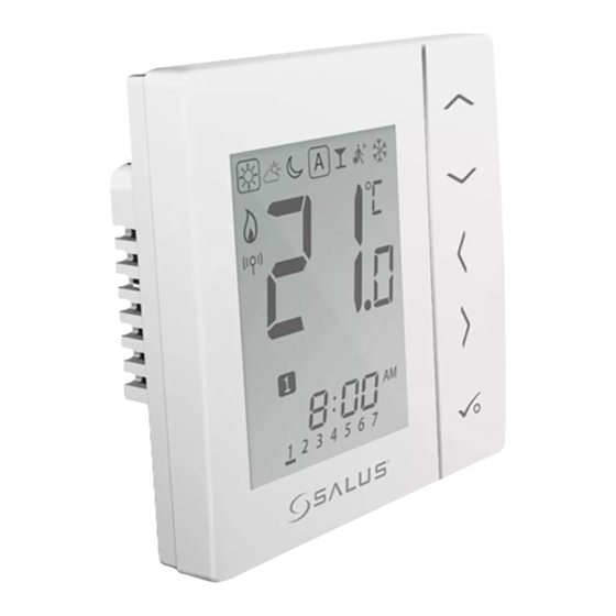
4 in 1 Digital Thermostat Control
Models: VS10W and VS10B
I N S TA L L E R / U S E R M A N U A L
Table of
Contents
Previous
Page
Next
Page
1
2
3
4
5
Advertisement
Table of Contents
Need help?
Do you have a question about the VS10W and is the answer not in the manual?
Ask a question
Questions and answers
Related Manuals for Salus VS10W
Temperature Controller Salus VS10B Installer's/User's Manual
4 in 1 digital thermostat control (77 pages)
Salus Controls DT600, DT600RF - Intelligent Temperature Controller Quick Guide
(article)
Temperature Controller Salus SP120 Instruction Manual
S-series single channel controller (27 pages)
Temperature Controller Salus iT500 Series User's Reference Manual
Thermostat, receiver, gateway (9 pages)
This manual is also suitable for:
Vs10b
Table of Contents
Save PDF
Print
Rename the bookmark
Delete bookmark?
Delete from my manuals?
Login
Sign In
OR
Sign in with Facebook
Sign in with Google
Upload manual
Upload from disk
Upload from URL


Need help?
Do you have a question about the VS10W and is the answer not in the manual?
Questions and answers