Table of Contents
Advertisement
Advertisement
Table of Contents

Subscribe to Our Youtube Channel
Related Manuals for Yamaha YZF-R1P


Summary of Contents for Yamaha YZF-R1P
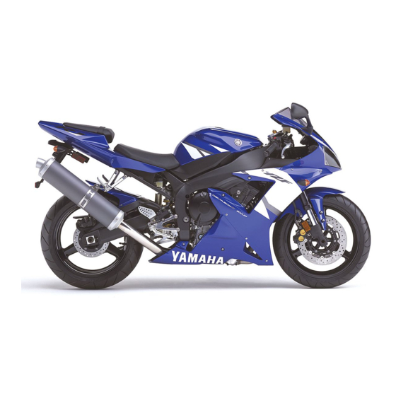
- Page 1 YZF-R1P YZF-R1PC ASSEMBLY MANUAL LIT-11666-15-47 5PW-28107-10 –1–...
-
Page 2: Symbols Used In Assembly Manual
Since some external parts of the In order to simplify descriptions in assembly manuals, motorcycle have been removed at the Yamaha factory for the the following symbols are used: convenience of packing, assembly by the Yamaha dealer is required. - Page 3 PREPARATION To assemble the motorcycle correctly, supplies and working space are required. Supplies oils, greases, shop rags. Workshop The workshop where the motorcycle is assembled should be clean and large. The floor should be level. Self-protection Protect your eyes with suitable safety spectacles or safety goggles when using compressed air, when grinding or when doing any operation which may cause particles to fly off.
- Page 4 UNPACKING 1. Remove the frame cover 1. NOTE: To remove the frame cover, cut the vinyl bands around the cover using a cutter or scissors. 2. Remove the bolts 2 (upper bracket). 3. Remove the bolt 3 (front tire). 4. Remove the packing frames 4 (upward and sideways). NOTE: Remove the bolts while holding frame.
-
Page 5: Parts Location
PARTS LOCATION 1 Carton box –2–... - Page 6 1 Carton box Vinyl bag 1 Plugs Screw, washer and special nuts Bolt (windscreen) (front master cylinder) (handle crown) Bolt Front reflector (handle crown and handlebar) (rear view mirror) (front reflector) Owner’s manual Rear view mirrors Windscreen –3–...
-
Page 7: Setup Procedures
SETUP PROCEDURES –4–... - Page 8 1. Handlebar Reservoir tank (brake) Hexagon socket bolt d = 6 (0.24),r= 12 (0.47) Crown nut Hexagon socket bolt d = 6 (0.24),r= 25 (0.98) Hexagon socket bolt d = 6 (0.24),r= 25 (0.98) A: Tighten the crown nut to specified C: Tighten the bolt to specified torque.
- Page 9 4. Rear view mirror Rear view mirror (left and right) d = 6 (0.24) Cap nut 5. Windscreen Windscreen Special nut d = 5 (0.20) Washer d = 5.5 (0.22) Screw d = 5 (0.20),r= 15 (0.59) CAUTION: The windscreen is made of an acrylate resin.
-
Page 10: Cable Routing
CABLE ROUTING CAUTION: Proper cable and lead routing is essential to insure safe machine operation. Clutch cable Å Pass the throttle cable in front of the brake hose. ı Pass the clutch cable behind the front fork. Ç In this area, the handlebar switch lead (right side) should not be in front of the throttle cable. - Page 11 1 (–) lead 2 (+) lead –8–...
- Page 12 ADJUSTMENTS AND PREDELIVERY SERVICE –9–...
-
Page 13: Checking And Charging The Battery
A. CHECKING AND CHARGING THE BATTERY NOTE: WARNING The battery used in this motorcycles is a new version • • • • • Do not attempt boost charging under any maintenance free “Valve Regulated Lead Acid circumstances. Battery”, it has been pre-filled with electrolyte at the •... -
Page 14: Checking The Engine Oil Level
EAA00129 C. CHECKING THE ENGINE OIL LEVEL 1.Stand the motorcycle on a level surface. NOTE: Recommended oil classification: API Service “SE”, NOTE: “SF” and “SG” type or equivalent (e.g. “SF-SE”, “SF- • Place the motorcycle on a suitable stand. SE-CC”, “SF-SE-SD” etc.). •... -
Page 15: Adjusting The Engine Idling Speed
EAA00140 E. ADJUSTING THE ENGINE IDLING SPEED NOTE: 2. Adjust: • Prior to adjusting the engine idling speed, the throttle engine idling speed body synchronization should be adjusted properly, the MMMMMMMMMMMMMMMMMMMMMMMMMMMMMMMMMMMM a. Turn the throttle stop screw 1 in direction a or b air filter should be clean, and the engine should have adequate compression. -
Page 16: Adjusting The Rear Brake
EAA00146 H. ADJUSTING THE REAR BRAKE c. Tighten the locknut 1 to specification. 1. Measure: • brake pedal position (distance a from the top of the rider footrest to the Locknut top of the brake pedal) 16 Nm (1.6 m • kg,12 ft • lb) Out of specification →... -
Page 17: Bleeding Brake System
Å EAA00154 J. BLEEDING HYDRAULIC BRAKE SYSTEM c. Connect a clear plastic hose 1 tightly to the bleed WARNING screw 2. Bleed the hydraulic brake system whenever: Å Front • • • • • the system was disassembled, ı Rear •... -
Page 18: Adjusting The Front Fork Legs
EAA00159 L. ADJUSTING THE FRONT FORK LEGS The following procedure applies to both of the front Rebound damping fork legs. CAUTION: WARNING Never go beyond the maximum or minimum • • • • • Always adjust both front fork legs evenly. adjustment positions. -
Page 19: Adjusting The Rear Shock Absorber Assembly
EAA00169 M. ADJUSTING THE REAR SHOCK ABSORBER ASSEMBLY Rebound damping WARNING Securely support the motorcycle so that there is CAUTION: no danger of it falling over. Never go beyond the maximum or minimum adjustment positions. Spring preload 1. Adjust : CAUTION: •... -
Page 20: Adjusting The Drive Chain Slack
EAA00178 N. ADJUSTING THE DRIVE CHAIN SLACK NOTE: 4. Loosen: • The drive chain slack must be checked at the tightest wheel axle nut 1 point on the chain. 5. Adjust: • drive chain slack CAUTION: MMMMMMMMMMMMMMMMMMMMMMMMMMMMMMMMMMMM a. Loosen both locknuts 2. A drive chain that is too tight will overload the b. -
Page 21: Adjusting The Digital Clock
EAA00185 Q. ADJUSTING THE DIGITAL CLOCK Turn the key to “ON”. To change the display to the clock mode, push the “SELECT” button 3 for at least one second. To change the display back to the prior mode, push the “SELECT”... - Page 22 APPENDICES SERVICE DATA YZF-R1P/YZF-R1PC Engine idling speed: 1,000 ~ 1,100 r/min Spark plug: Type CR9EIA 9 (NGK), IU27D (DENSO) 0.8 ~ 0.9 mm (0.031 ~ 0.035 in) Fuel: Recommended fuel Premium unleaded gasoline only Fuel tank capacity Total: 17 L (3.74 Imp gal, 4.49 US gal) Valve clearance (cold): 0.11 ~ 0.20 mm (0.0043 ~ 0.0079 in)
- Page 23 TIGHTENING TORQUE Tightening torque Thread size Part to be tightened m • kg ft • lb Engine: Spark plugs Engine oil drain bolt Chassis: Upper bracket and front fork Steering stem nut 11.5 Handlebar and front fork Handlebar and upper bracket Lower ring nut See NOTE Lower bracket pinch bolts...
- Page 24 Tightening torque Thread size Part to be tightened m • kg ft • lb Lean angle cut-off switch sensor and battery box Rider footrest bracket and frame Passenger footrest bracket and frame Rear master cylinder Rear brake hose union bolts Sidestand Front wheel axle and bolt Rear wheel axle nut...
- Page 26 YAMAHA MOTOR CO., LTD. 2500 SHINGAI IWATA SHIZUOKA JAPAN PRINTED IN U.S.A. –2–...
Need help?
Do you have a question about the YZF-R1P and is the answer not in the manual?
Questions and answers