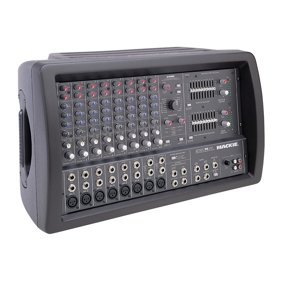
Mackie 406M Service Manual
Ppm series
Hide thumbs
Also See for 406M:
- Specifications (6 pages) ,
- Hook-up manual (7 pages) ,
- Owner's manual (36 pages)
Advertisement
Table of Contents
PPM series
Professional Powered Mixers:
406M, 408M, 808M, 408S and 808S
1
2
3
U
U
U
MON
MON
MON
+15
+15
+15
O O
O O
O O
O O
U
U
U
EFX
EFX
EFX
+10
+10
+10
O O
O O
O O
O O
U
U
U
HI
HI
HI
12kHz
12kHz
12kHz
-15
+15
-15
+15
-15
+15
-15
U
U
U
MID
MID
MID
2.5kHz
2.5kHz
2.5kHz
-12
+12
-12
+12
-12
+12
-12
U
U
U
LOW
LOW
LOW
80Hz
80Hz
80Hz
-15
+15
-15
+15
-15
+15
-15
PAN
PAN
PAN
L
R
L
R
L
R
L
NORMAL
INPUT
NORMAL
INPUT
NORMAL
INPUT
NORMAL
LEVEL
LEVEL
LEVEL
SET
SET
SET
LOW
HI
LOW
HI
LOW
HI
LOW
U
U
U
O O
+20dB
O O
+20dB
O O
+20dB
1
2
3
VOLUME CH.
VOLUME CH.
VOLUME CH.
VOLUME CH.
INSERT
INSERT
INSERT
LINE
LINE
LINE
1
2
3
MIC
MIC
MIC
SERVICE MANUAL
4
5
6
7
8
U
U
U
U
U
MON
MON
MON
MON
MON
+15
+15
+15
+15
+15
O O
O O
O O
O O
U
U
U
U
U
EFX
EFX
EFX
EFX
EFX
+10
+10
+10
+10
+10
O O
O O
O O
O O
U
U
U
U
U
HI
HI
HI
HI
HI
12kHz
12kHz
12kHz
12kHz
12kHz
+15
-15
+15
-15
+15
-15
+15
-15
+15
U
U
U
U
U
MID
MID
MID
MID
MID
2.5kHz
2.5kHz
2.5kHz
2.5kHz
2.5kHz
+12
-12
+12
-12
+12
-12
+12
-12
+12
U
U
U
U
U
LOW
LOW
LOW
LOW
LOW
80Hz
80Hz
80Hz
80Hz
80Hz
+15
-15
+15
-15
+15
-15
+15
-15
+15
PAN
PAN
PAN
PAN
PAN
R
L
R
L
R
L
R
L
R
INPUT
NORMAL
INPUT
NORMAL
INPUT
NORMAL
INPUT
NORMAL
INPUT
LEVEL
LEVEL
LEVEL
LEVEL
LEVEL
SET
SET
SET
SET
SET
HI
LOW
HI
LOW
HI
LOW
HI
LOW
HI
U
U
U
U
U
O O
+20dB
O O
+20dB
O O
+20dB
O O
+20dB
O O
+20dB
4
5
6
7
8
VOLUME CH.
VOLUME CH.
VOLUME CH.
VOLUME CH.
INSERT
INSERT
INSERT
LEFT/MONO
LEFT/MONO
STEREO
STEREO
MIC/
MIC/
LINE
LINE
LINE
RIGHT
RIGHT
LINE
LINE
HI-Z
HI-Z
4
5
6
7
8
MIC
MIC
MIC
MIC
MIC
POWER
MASTER OUTPUT SECTION
CUSTOM 32-BIT PRECISION
DIGITAL STEREO EFFECTS PROCESSING
NORMAL
63
125
250
500
1K
2K
4K
+15
10
EFX
CLIP
EFX BYPASS
5
0
12
EFX DRIVE
0
LEVEL
5
EFX WIDE
10
REVERSE
DELAY 1
-15
GATED
DELAY 2
CATHEDRAL
DELAY 3
LG. HALL
DELAY 4
MONITOR EQUALIZER
MD. HALL
CHORUS
LG. PLATE
FLANGE
75Hz RUMBLE
MD. PLATE
PHASER
REDUCTION
SM. ROOM
SPRING
63
125
250
500
1K
2K
4K
PARAMETERS
NORMAL
NORMAL
+15
10
5
0
0
10
0
10
TIME
DAMPING
5
REVERBS
DELAYS
10
RATE
DEPTH
CHORUS
-15
FLANGE
PHASER
MAIN-STEREO/MONO EQUALIZER
75Hz RUMBLE
PHANTOM
BREAK
POWER CH 1 -8
(MUTES CH 1-6)
REDUCTION
POWER AMP ROUTING
808S
2 X 600W STEREO
STEREO MAINS
LEFT = MAIN
RIGHT = MONITOR
EFFECTS
(OVERRIDES INTERNAL EFX)
MAINS
MONITOR
EFX FOOT
L POWER
R POWER
LINE
SWITCH
SEND
AMP IN
AMP IN
OUT
LEFT RETURN
RIGHT RETURN
L MIXER OUT
R MIXER OUT
COMPRESSOR
OUT
IN
©1999, ©2000 MACKIE DESIGNS, INC.
LEVEL
8K
16K
U
CLIP
15+
5
10
+10
O O
0
5
EFX TO
MON
5
0
U
10
5
15
10
20
15-
30
+12dB
O O
MONITOR
MASTER
8K
16K
LEVEL
U
CLIP
15+
5
10
O O
+10
0
5
EFX TO
MAIN
5
0
U
10
5
15
10
20
15-
30
+12dB
O O
MAIN
L
R
MASTER
TAPE IN
U
L
R
+15
O O
LEVEL
R
L
TAPE OUT
820-185-00
Advertisement
Table of Contents


Need help?
Do you have a question about the 406M and is the answer not in the manual?
Questions and answers