Advertisement
KSACN0101CAC
KSACN0101AAA
SAFETY CONSIDERATIONS
Installing, starting up, and servicing air- conditioning equipment
can be hazardous due to system pressures, electrical components,
and equipment location (roofs, elevated structures, etc.).
Only trained, qualified installers and service mechanics should
install, start- up, and service this equipment.
Untrained personnel can perform basic maintenance functions
such as cleaning coils. All other operations should be performed
by trained service personnel.
When working on the equipment, observe precautions in the
literature and on tags, stickers, and labels attached to the
equipment.
Follow all safety codes. Wear safety glasses and work gloves.
Keep a quenching cloth and fire extinguisher nearby when
brazing. Use care in handling, rigging, and setting bulky
equipment.
Read these instructions thoroughly and follow all warnings or
cautions included in literature and attached to the unit. Consult
local building codes and National Electrical Code (NEC) for
special requirements. Recognize safety information. This is the
! !
safety- alert symbol
. When you see this symbol on the unit and
in instructions or manuals, be alert to the potential for personal
injury. Understand these signal words: DANGER, WARNING,
and CAUTION.
These words are used with the safety- alert
symbol. DANGER identifies the most serious hazards which will
result in severe personal injury or death. WARNING signifies
hazards which could result in personal injury or death. CAUTION
is used to identify unsafe practices which may result in minor
personal injury or product and property damage. NOTE is used to
highlight suggestions which will result in enhanced installation,
reliability, or operation.
WARNING
!
ELECTRICAL SHOCK HAZARD
Failure to follow this warning could result in personal injury or
death.
Before beginning any modification or installation of this kit, be
sure the main electrical disconnect is in the OFF position.
Ensure power is disconnected to the fan coil unit. On some
systems both the fan coil and the outdoor unit may be on the
same disconnect. Tag the disconnect switch with a suitable
warning label. There may be more than one disconnect.
CAUTION
!
EQUIPMENT DAMAGE HAZARD
Failure to follow this warning may result in equipment
damage.
Do not install wired controller in an area subjected to excessive
steam, oil or sulfide gas. Doing so may cause the controller to
deform and/or fail.
Owner's Manual
Kit Contents: Confirm that all the following parts are included.
Field Supplied Components: Prepare the following on site.
S This manual contains installation procedures for the wire
S Install the wire joint (5p) to the appointed position of the electric
S The wired controller circuit is a low voltage circuit. Never
S The shield cable must be connected stable to the ground or the
S Do not extend the shield cable by cutting. If necessary, use a
S After finishing the connection, do not use a Meggar to perform
Wired Remote Controller
Ductless Split Systems
No.
Description
1
Wired Remote Controller
Installation and owner's
2
manual
3
Screws
4
Wall plugs
5
Screws
6
Plastic screw bars
7
The connective wires group
Description
Qty
Switch Box
1
Wiring Tube
(insulating sleeve and
1
tightening screw)
controller only. Refer to the indoor unit Installation Manual for
connecting the Wire Controller and the Indoor Unit.
controlling box.
connect it with a standard 220V/380V circuit or place it in the
same wiring tube as the circuit. The interval must be more than
11.8- 19.7in. (300~500mm).
transmission may fail.
Terminal Connection Block to connect.
the installation check to the signal wire.
Qty
Remarks
1
n/a
1
n/a
M4X20 (for mount-
3
ing on the wall)
3
For wall mounting
M4X25 (for mount-
2
ing on the wall)
For fixing on the
2
switch box
1
24AWG
Type
Remarks
n/a
n/a
n/a
n/a
Advertisement
Table of Contents

Related Manuals for CAC / BDP KSACN0101CAC

Summary of Contents for CAC / BDP KSACN0101CAC
-
Page 1: Safety Considerations
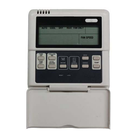
KSACN0101CAC Wired Remote Controller KSACN0101AAA Ductless Split Systems Owner’s Manual SAFETY CONSIDERATIONS Installing, starting up, and servicing air- conditioning equipment can be hazardous due to system pressures, electrical components, and equipment location (roofs, elevated structures, etc.). Only trained, qualified installers and service mechanics should install, start- up, and service this equipment. - Page 2 CONTROLLER INDICATOR NAMES AND FUNCTIONS 1. OPERATION MODE INDICATION 4. ON/OFF INDICATOR Press the MODE button to select the following modes: AUTO, The icon displays when the indicator is on. COOL, DRY, HEAT, FAN ONLY, and AUTO. The HEAT mode 5.
-
Page 3: Installation Method
INSTALLATION METHOD When a wired remote controller is needed, add a small 5- way terminal and secure an infrared emitter with gumwater near the receiver on the switch board. Connect the anode and cathode A and B, and +5V, GND, RUN to , C, D, E to the switch board. - Page 4 WIRED CONTROLLER BUTTONS NAMES AND OPERATIONS 1. MODE BUTTON 7. ON/OFF BUTTON Press this button to change the operation mode in the following When the unit is off, press this button and the indicator displays, sequence: AUTO, COOL DRY, HEAT, FAN, and back to AUTO. the wire controller powers on and sends the setting information to the indoor PCB.
-
Page 5: Timer Setting
TIMER SETTING 13. LOCK BUTTON (hidden) Press the LOCK button and all the current settings are locked. The Timer on only wire controller will not accept any operation except the LOCK 1. Press the TIME ON button and it displays SET on the LCD button. - Page 6 Catalog No: OMKSACN0101- 01 Copyright 2015 CAC / BDP S 7310 W. Morris St. S Indianapolis, IN 46231 Edition Date: 02/15 Replaces: NEW Manufacturer reserves the right to change, at any time, specifications and designs without notice and without obligations.
Need help?
Do you have a question about the KSACN0101CAC and is the answer not in the manual?
Questions and answers