Table of Contents
Advertisement
Quick Links
Advertisement
Table of Contents

Related Manuals for Chamberlain LiftMaster Q


Summary of Contents for Chamberlain LiftMaster Q
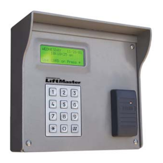
- Page 1 LiftMaster Q Access Keypad Installation Manual...
- Page 2 Thank you for purchasing the LiftMaster Q Access Keypad. Every effort has been made to ensure the accuracy of the information in this document. LiftMaster assumes no liability for any inaccuracies contained herein. LiftMaster reserves the right to change the information contained herein at any time and without notice.
-
Page 3: Table Of Contents
Table of Contents Introduction....................1 Features and Options ................1 Q Access Keypad ................1 Wiegand Reader................1 Pinhole Camera................1 Device Tamper .................1 Input/Output..................2 Technical Specifications................2 Installation Instructions................3 Selecting the Mounting Location............3 Drive Up Accessibility ...............3 Walk Up Accessibility ...............3 Determining the proper mounting height ..........4 Mounting Types ..................4 Gooseneck Stand Mount..............5 Wall Mount..................6... - Page 4 System Maintenance................31 Periodic Visual Inspection..............31 Periodic Cleaning................31 Cleaning the Housing and Touchpad ..........31 Cleaning the Magnetic Stripe Reader ..........32 Troubleshooting ..................32 Test power and communication............33 Test card and code input ..............34 Test individual devices................36 Test multiple devices or entire site .............36 List of Figures 1 - V ..
-
Page 5: Introduction
Test individual devices To test individual devices, use the following procedure: The LiftMaster Q Access Keypad is a powerful tool for controlling entry to 1. Try a code or card at the AI device controlling the gate. Be sure the or exit from a secured area. -
Page 6: Input/Output
4. If there are multiple problems or ongoing issues, the process in the Input/Output previous step can be performed for an entire site. Generally, multiple The Q Access Keypad is equipped with two output relays and four problems are a sign of problems in the wiring, either from bad splices, factory dry contact inputs. -
Page 7: Installation Instructions
Installation Instructions Step 6 Are any other devices set to the same address as the Q Access The first step in installation is to determine where and how the Q Access Keypad? Keypad will be installed. Yes – Change one of the devices and retest No –... -
Page 8: Determining The Proper Mounting Height
Test power and communication Step 1 Does the Q Access Keypad have Power? Yes – Proceed to step 2 No – Check Power Supply and Wiring and retest or see Multiple Device Problems This can be tested quickly by checking the display of the keypad. If the display is on or if any of the LEDs on the board are on, the board has power. -
Page 9: Gooseneck Stand Mount
Additional cards can be ordered from gooseneck stand to the concrete base. Chamberlain Access Solutions. It is advisable to keep a supply of cards on hand. The actual location of the gooseneck and the mounting techniques used may be affected by local building codes. -
Page 10: Wall Mount
System Maintenance Wall Mount The Q Access Keypad requires a minimal amount of maintenance. When The Q Access Keypad housing will mount easily to a wall. The type of the recommended maintenance is done as specified, the keypad will fastener required depends on the material used to construct the wall. If provide the best possible security for your site. -
Page 11: Connecting The Q Access Keypad
When the customer’s card has expired: Connecting the Q Access Keypad The installation methods used are critical to ensure trouble-free * WE’RE SORRY * operation of the Q Access Keypad. Most of the problems that occur over time can be traced back to poor installation techniques or improper THE CARD YOU ENTERED wiring. -
Page 12: Connecting The Video Camera
All wiring to the Q Access Keypad is done through removable terminal Access Response Messages block connectors. The connector on the left (P1) has all of the There are several standard messages built in to the Q Access Keypad. connections for the power and data communication wiring. The The types of messages the keypad receives from the controller in connector on the right (P4) connects to a gate operator or door strike. -
Page 13: Connecting To A Gate Operator
The display and keypad are backlit at a low level to conserve power when no one is using the device. This low level is sufficient to read the display at night. As soon as a customer touches a key, the display comes on to full brightness, making it easier to read the instructions. -
Page 14: Connecting To A Door Strike
block at the lower right corner of the board (P4). Make sure the signal Maximum Attempts Check from the operator meets the electrical specifications for the relays. DO The maximum attempts security check is designed to discourage NOT USE ANY HIGH VOLTAGE SIGNALS. The pin connections for the someone from attempting numbers at random to enter the site. -
Page 15: Figure 7: Door Strike Wiring
Security Checks A series of security checks are performed by the Q Access Keypad before allowing entrance. These checks are used to prevent unauthorized access attempts. When a customer uses an access code, the checks are performed as soon as the code is entered. If the customer uses a card, the checks are performed as soon as the card has been swiped in the magnetic stripe reader or presented to the proximity reader. -
Page 16: Operating The Q Access Keypad
Operating the Q Access Keypad The user enters their access code using the touchpad and presses the # key. The keypad will send the code to the controller and wait for a response while the keypad goes through the security checks described in the Security Checks section. -
Page 17: Dry Contact Inputs
Hold Open by Time Optional Custom Message When two gates are used, it is sometimes necessary to hold the The third message the keypad can display when no keys have been secondary gate open during certain hours. The “Hold Open by Time” pressed and no cards used. -
Page 18: Using Extended Door Controls
Inputs 1 and 2 – Extended Door Controls Standard Display Messages When extended door controls are set, Input 1 is used for the door contact The Q Access Keypad has two standard messages and one optional and Input 2 is used for a request to exit device contact. See Using message that are displayed when the power is on and no other functions Extended Door Controls for more information. -
Page 19: Q Access Keypad Setup Function
The basic operation of this function depends on having a door equipped Allows the displayed site name to be changed. If Change the Displayed with both a door strike and a door alarm contact. The door strike is Site Name? YES is selected, setup will proceed to the Press * for YES following step. -
Page 20: Setup Parameters / Functions
There are three (3) ways to exit the setup mode: you can press the 7, 8, Sets the amount of time the keypad should Current Comm. Off and 9 keys simultaneously, press the program button on the circuit Time (seconds) 005 wait before considering it has lost board, or go through all of the setup functions. - Page 21 At this point, the basic parameters required for operation have been Sets the time of day on Sunday that Relay 2 Enter SUNDAY entered. If no other options are active or required, you can exit the setup will activate. OPEN Time mode by pressing the program button on the circuit board or by pressing PRESS # WHEN DONE the 7, 8, and 9 keys simultaneously.
- Page 22 Displays customer messages in one of seven When Relay #2 is set for: Activates Relay 2 when a system alarm occurs, Current Language: ENGLISH languages. Setup functions are in English only. allowing the relay to be used to control an ALARM OUTPUT Press * to Change The other languages are French, Spanish,...