Advertisement
Table of Contents
- 1 Table of Contents
- 2 Warnings and Precautions for Safety
- 3 Specification
- 4 Name of each Part
- 5 Cold Air Circulation
- 6 Wiring Diagram
- 7 Pcb Circuit Diagram
- 8 How to Replace the Parts
- 9 Pcb Control Function
- 10 Temperature Control of Refrigerator Compartment
- 11 Explode View and Parts List
- Download this manual
Advertisement
Table of Contents

Related Manuals for Daewoo FR-650NT Series


Summary of Contents for Daewoo FR-650NT Series
- Page 1 FRS5100002 FN-510DW FR-650NT.. FR-650NW.. FN-650NT.. FN-650NW.. FN-510DW FR-651NT.. FN-651NW FN-651NT.. FR-651NW.. FN-651NW same as FN510DW Sep. 2011.
-
Page 2: Table Of Contents
C O N T E N T S WARNINGS AND PRECAUTIONS FOR SAFETY -------------------------------- 2 1. SPECIFICATION ----------------------------------------------------------------------- 3 2. NAME OF EACH PART -------------------------------------------------------------- 4 3. COLD AIR CIRCULATION ---------------------------------------------------------- 6 4. WIRING DIAGRAM -------------------------------------------------------------------- 7 5. PCB CIRCUIT DIAGRAM ------------------------------------------------------------ 8 6. -
Page 3: Warnings And Precautions For Safety
WARNINGS AND PRECAUTIONS FOR SAFETY Please observe the following safety precautions in order to use safely and correctly the refrigerator and to prevent accident and danger during repair. 1. Be care of an electric shock. Disconnect power cord from wall outlet and wait for more than three minutes before replacing PCB parts. -
Page 4: Specification
1. SPECIFICATION Item Specification Total 525 Li ISO Gross Volume Freezer Compartment 163 Li (Li) Fresh Food Compartment 362 Li Total 492 Li ISO Storage Volume Freezer 142 Li (Li) (Li) Refrigerator 350 Li Non dispenser model 84Kg Weight Dispenser model 85Kg External Non dispenser model... -
Page 5: Name Of Each Part
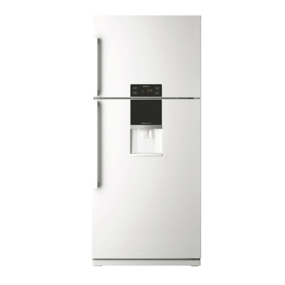
2. Name Of Each Part Non Dispenser Model 1. Freezer Compartment LED Lamp 6. Fresh Food Compartment Sensor 2. Freezer Compartment Shelf 7. Vegetable Case 3. Freezer Compartment Temperature Controller 8. Freezer Compartment Pockets 4. Fresh Food Compartment LED Lamp 9. - Page 6 Dispenser Model 1. Freezer Compartment LED Lamp 6. Fresh Food Compartment Sensor 2. Freezer Compartment Shelf 7. Vegetable Case 3. Freezer Compartment Temperature Controller 8. Freezer Compartment Pockets 4. Fresh Food Compartment Lamp 9. Water Tank 5. Fresh Food Compartment Shelves 10.
-
Page 7: Cold Air Circulation
3. Cold Air Circulation... -
Page 8: Wiring Diagram
4. Wiring Diagram... -
Page 9: Pcb Circuit Diagram
5. PCB CIRCUIT DIAGRAMS... -
Page 10: How To Replace The Parts
6. How To Replace The Parts 6-1. Freezer Louver Part Ph t Photos Description i ti - Remove ‘Freezer Shelf’ at first. - Remove 4 screws on ‘Freezer Louver’. e o e sc e s o ee e ou e - Pull forward the ‘Freezer Louver’. - Page 11 6-2. Cover Fan F As Photos Description - Remove ‘Cover Fan B’. Cover Fan B Cover Fan B - Replace ‘Knob F Control’.
- Page 12 6-3. Freezer Motor As Photos Description - Remove 2 screws. - Remove Clamp Fan with pliers and then disassemble ‘Fan’ with (-) driver. - Unscrew the earth wire bolt. - Remove the screws holding the bracket. - Now disassemble the ‘Freezer Motor’.
- Page 13 6-4. Evaporator Photos Description - Remove the screw which fixes evaporator. - Pull forward the evaporator and pipes. - Be careful not to bend the pipes. Defrost Heater < Defrost Heater > - Disconnect ‘Defrost Heater’ lead wire on the right. - Disconnect ‘Temperature Fuse’...
- Page 14 6-5. M/Flow-Duct Photos Description - Remove ‘Deco M/F Duct’ with (-) driver. - Remove ‘Cover sensor’ with (-) driver. - Disconnect ‘R Senosr ‘ lead wire. - Remove the screws on the ‘ Cover M/F Duct’. - Separate Cover M/F Duct with Insulator. - Disassemble the R ‘Sensor ‘...
- Page 15 6-6. LED Lamps Freezer compartment LED lamp Photos Description - Remove ‘Freezer Lamp Window’. - Be careful not to damage the hook. - Unlock the hook on the side of ‘Fixture lamp’ and disassemble the LED lamp. - Disconnect ‘LED Lamp’ lead wire. Fresh Food compartment LED lamp Photos Description...
- Page 16 6-7. Handle Installation Photos Description - Attach the ‘Fixture’ on the cabinet and Screw the bolt. - Align door handle with fixture and pull the handle down ( Be careful the direction) - Fasten the screw in the hold of handle.
- Page 17 6-8. Front PCB Photos Description - Unlock the hook on the botton of the ‘Front PCB ‘ with (-) driver. - Disassemble the ‘Front PCB’. - Disconnect ‘Front PCB‘ lead wire.
- Page 18 6-9. MAIN PCB Photos Description -Remove the screws and disassemble the ‘Grille As’. - Remove the screws and disassemble the ‘Box Main PCB As’. - Disconnect Hosings on the ‘Main PCB’.
- Page 19 6-10. Water Dispenser Photos Description - Push the ‘Stopper Water Tank‘, then pull and remove the ‘Water Tank As’. - Remove the screws on the bottom of ‘Panel Dispns As’. - Disassemble the ‘Panel Dispns As’.
-
Page 20: Pcb Control Function
7. PCB CONTROL FUNCTION 7-1. DISPLAY INPUT CONTROL OBJECT PCB Control Panel Buttons PCB Control Panel LED ● ● Temperature adjustment button for refrigerator “Super Cool” button compartment.(+) Temperature adjustment button for refrigerator “SAVE” button compartment.(-) REFERENCE PAGE LED DISPLAY FUNCTION OPERATION LED “3”... -
Page 21: Temperature Control Of Refrigerator Compartment
7-2. Temperature Control of Refrigerator Compartment INPUT CONTROL OBJECT PCB Control Panel “TEMP” Buttons PCB Control Panel LED ● ● R-sensor COMPRESSOR, FAN ● ● A. “TEMP UP, DOWN” Button ⓐ Temperature control of Refrigerator compartment ⓑ 5 step mode of successive temperature mode ⓒ... - Page 22 7-3. Defrost Mode INPUT CONTROL OBJECT Total COMP Work Time COMP Working Rate ● ● Defrost Mode ● Total Door Open Time ● ● Conditions of Defrost Mode ● A. When total operation time of compressor becomes: 6, 8, 10, 12 hours. ⓐ...
- Page 23 7-3. Defrost Mode INPUT CONTROL OBJECT Total COMP Work Time COMP Working Rate ● ● Defrost Mode ● Total Door Open Time ● ● Initial Defrost ● A. In providing initial power or returning power failure, if the temperature at the D sensor is under 3 5°C Defrost Mode starts (It proceeds from “PRE COOL” ) if the temperature at the D-sensor is under 3.5 C, Defrost Mode starts.
- Page 24 7-4. Function of Low Ambient Temperature (RT) INPUT CONTROL OBJECT R-HTR ● ● COMP ● A. Condition of LOW RT ⓐ LOW RT Period : RT sensor ≤ 19°C ⓑ When the temperature of RT sensor is over 20°C, the system comes to be “General Operation Mode”. ⓒ...
- Page 25 7-7. Short Circuit Test ( Pull Down Test ) INPUT CONTROL OBJECT “SAVE, DOWN” Button COMP & FAN ● ● A. How to start: by pressing “SAVE” button for continuously and “DOWN” button 10 times continuously. B. How to confirm: by pressing “UP” button for continuously and “DOWN” button 5 times. And then, the mode displays.
- Page 26 7-10. Control of R-sensor OFF Point INPUT CONTROL OBJECT ”J1” On Main PCB Control Resistance of R sensor OFF Point ● ● A. LOW COOLING OPTION - When the refrigeration of refrigerator is poor or weak though Fan and COMP are working continuously, the following actions are recommended for service.
- Page 27 7-11. Error Display INPUT CONTROL OBJECT PCB Control Panel Buttons Door LED Lamp ● ● ● - ERROR DISPLAY - To confirm error happens or not, push “UP” button for continuously and “DOWN” button 5 times. - To stop the Error Display Set, push “SAVE” button 1 times, or wait 4 minutes. - After operations back to normal, the displays come to be reset.
-
Page 28: Explode View And Parts List
Cabinet PART-CODE PART NAME SPEC. Q'ty 3000066310 ASSY CAB URT FRP-510,DIGITAL 3001445400 COVER *T HI PP J-370A, FRP-512 3012935400 HINGE *T AS SHP1 2.6T, FPR-512 3018100010 SWITCH DR 2 BUTTON/4P,DSD-5 3012935500 HINGE *M AS SHP1 4T MFZN FRP-512 3012543200 GUIDE C/C *L AS FRP-512, GUIDE+ROLLER 3012543300 GUIDE C/C *R AS... - Page 29 Machine Room PART-CODE PART NAME SPEC. Q'ty 3010345201 BASE COMP AS FR-B512FH OPTION CORD POWER AS 3956126S51 HPL26YH-5-K, 220-240V/50HZ 3956112250 DG125E11RAW5 220-240V/50HZ 3956183Q5B MK183Q-L2UB/DW2 220-240V/50HZ COMPRESSOR 3953158K20 YX58LHE2 127V/60HZ 3953158K30 YF58LHE3 110V/60HZ 3956162D4A MK162B-LIUA 220V/60HZ 3016007000 SPECIAL WASHER SBHG T0.6 3010101600 ABSORBER COMP R-134a...
- Page 30 Freezer / Refrigerator Compartment PART-CODE PART NAME SPEC. Q'ty 3017065500 FRP-510 EVA AS 3017068300 FRP-510(R600a) 3012823100 HEATER SHEATH AS 230V 200W R-600a 301281010 HEATER D AS 230V 250W R-134A 3017202700 FR-B512FH FUSE TEMP AS 3017203220 FR-510C(R600A) 3012767700 NBC-K43-D24(PBN-43) R-134a HARNESS D SENS 3012767710 GERNERAL (0D8) TPYE R-600a 3012530800...
- Page 31 Freezer / Refrigerator Door Q'ty PART-CODE PART NAME SPEC. 650NT 650NW 651NT 651NW 300009C700 TITANIUM PCM 300009C710 TITANIUM ELLIO 300009C720 M/WHITE EMBO 300009C730 TITANIUM VCM ASSY F DR 30100B5300 TITANIUM PCM 30100B5310 TITANIUM ELLIO 30100B5320 M/WHITE EMBO 30100B5330 TITANIUM VCM 3012320200 GASKET F DR AS PVC, GRAY...
Need help?
Do you have a question about the FR-650NT Series and is the answer not in the manual?
Questions and answers