Daewoo FR-631ND Service Manual
Hide thumbs
Also See for FR-631ND:
- User manual (7 pages) ,
- Installation instructions manual (7 pages) ,
- Service manual (21 pages)

Related Manuals for Daewoo FR-631ND


Summary of Contents for Daewoo FR-631ND
- Page 1 S/M No. : FR631ND010 Service Manual Refrigerator Model: FR-631ND FR-710ND DAEWOO ELECTRONICS CO., LTD. http://svc.dwe.co.kr Feb. 2001...
-
Page 2: Table Of Contents
SAFETY AND PRECAUTIONS 1) For starters, be sure to check any chances of the leakage of electricity 2) You could handle a part in the vicinity of electricity after unplugging 3) You should put on rubber glovers to prevent an electric shock on operation test 4) Make sure the rated current, voltage, capacity before using an instrument 5) Keep your wet hands away from the metal goods in the freezer compartment not to be frostbitten 6) Be careful not to let water to permeate the electric part in the machine room... -
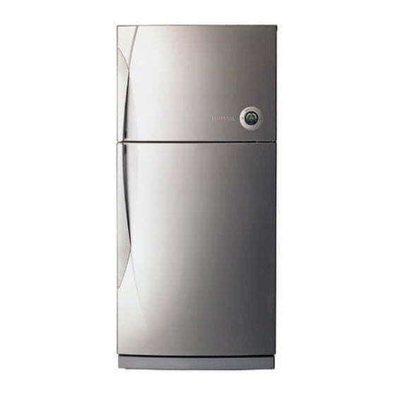
Page 3: External Views
1. EXTERNAL VIEWS 1-1. EXTERNAL SIZE 12.5 model FR-631ND FR-710ND 1-2. NAME OF PARTS 1 Freezer Compartment Lamp 2 Shelf Ffreezer 3 Case Icing 4 Guide Icing 5 Ice Box 6 Refrigerator Compartment Lamp 7 Cover Cubic Duct 8 Fresh Case... -
Page 4: Specifications
2. SPECIFICATIONS 2-1. OUTLINE DIVISION CONTENTS MODEL NAME FR-631ND FR-710ND FREEZER USABLE CAPACITY (L) REFRIGERATOR TOTAL WIDTH EXTERNAL DIMENSION( mm) DEPTH HEIGHT 1818 1818 REFRIGENT R134a COOLING SYSTEM Fan Cooling System COOLING &CONTROL SYSTEM DEFROST SYSTEM Fin Evaporator Forced DEFORST CONTROL Automatic Start &... -
Page 5: R134A
2) RELAY REFRIGERANT 220/50 VOLTAGE (V/HZ) 100 /50,60 110 / 60 115,120/60 127/60 220 / 60 230 / 50 240 / 50 TYPE NAME 276THBYY-52 181SHBYY-52 276THBYY-52 276THBYY-52 ASSY PART CODE 3018119350 3018116610 3018119350 3018119350 RESIS-TANCE C-RELAY PART CODE RESIS-TANCE S220 S330 S220... - Page 6 4) RUNNING CAPACITOR REFRIGERANT 220/50 VOLTAGE (V/HZ) 100 /50,60 110 / 60 115,120/60 127/60 220 / 60 230 / 50 240 / 50 PART CODE 400EL15110 RATED VOLTAGE 350V RATED CAPACITANCE 5µF REFRIGERANT R134a 220/50 VOLTAGE (V/HZ) 100 /50,60 110 / 60 115,120/60 127/60 220 / 60...
- Page 7 8) DEFROST HEATER REFRIGERANT R12, R134a 220/50 VOLTAGE (V/HZ) 100 /50,60 110 / 60 115,120/60 127/60 220 / 60 230 / 50 240 / 50 SPEC (W) 180W 180W 180W 180W 180W 180W 180W PART CODE 3012803210 3012803210 3012803210 3012803200 3012803200 3012803200 3012803200 9) LAMP ASSEMBLY REFRIGERANT...
- Page 8 13) DOOR S/W REFRIGERANT R12,R134a 220/50 VOLTAGE (V/HZ) 100 /50,60 110 / 60 115,120/60 127/60 220 / 60 230 / 50 240 / 50 TYPE NAME PART CODE 3018100010 3018100010 3018100010 3018100010 3018100010 3018100010 3018100010 14) F-SENSER REFRIGERANT R12,R134a 220/50 VOLTAGE (V/HZ) 100 /50,60 110 / 60...
-
Page 9: Power Cord
2-3. POWER CORD SHAPE OF POWER CORD PART CODE DESCRIPTION REMARK 3011315000 CP-2PIN For european country 401RA17200 CP-2PIN For other country 4006D17101 KP-30 For America & El Salvador 401PD17101 KP-211 For Japan & Taiwan 3011300801 BP-3PIN 3011303010 # 267 For Chile 3011315310 For Israel "For U.K, Middle Asia... -
Page 10: Door Color
2-4. DOOR COLOR 1) ASSEMBLY URETHAN FREEZER DOOR 1 NON-KEY TYPE R134a Refrigerant COLORTYP Embo High-glossy Normal High-glossy Embo High-glossy Normal PCM High-glossy Laminasheet Bright PCM Laminasheet Bright PCM PARTCODE 3010024400 3010024410 3010024420 2 KEY TYPE R134a Refrigerant COLORTYP Embo High-glossy Normal High-glossy... -
Page 11: Operation And Fuctions
3. OPERATION AND FUCTIONS 1. Fufrosting Mode 1-1. DISPLAY Input Control Object Contents Remark CUSTOM LED 1. Normal Operation F-PCB Button 1) SLEEP Icon(Amber):OFF FRZ.SET, 2) Initial Temperature Setting: REF.SET, Freezer/Refrigerator=middle/middle SLEEP 3) Radar:in rotation 4) EXERGY CONTROL, FRZ/REF:On 5) Else: CUSTOM Normal Silent... -
Page 12: Freezer Temperature Control
1-2. Freezer Temperature Control Input Control Object Contents Remark 1. COMP 1. Temperature mode changes with whenever the FRZ.SET Button is * ON / OFF 1. Freezer 2. F-FAN pushed. Diff : Fixed Temperatur by MI-COM e Button (Weak) --> Weak --> Middle --> Strong --> Quick FRZ. 2. -
Page 13: Refrigerator Temperature Control
1-3. Refrigerator Temperature Control Input Control Object Contents Remark 1. COMP 1. Temperature mode changes with whenever the REF.SET Button is * ON / OFF 1. Refrigerator 2. R-FAN pushed. Diff. : Fixed Temperatur by MI-COM e Button Weak --> Middle --> Strong --> Quick REF. --> Weak 2. -
Page 14: Sleep Mode
1-4. Sleep Mode Input Control Object Contents Remark 1. COMP 1. The mode starts with push of Sleep Button. 1. SLEEP 2. R-FAN Button 3. F-FAN 2. Terms to start Sleep Mode 2. RT-Sensor F-Sensor ≤-13°C 4. Custom LED Reinput within 40 minutes after the termination of Sleep mode F-Sensor Error Door Switch Error In Defrosting (Heater Defrosting, Pause, Fan Delay) - Page 15 1-5. Silent Mode Input Control Object Contents Remark 1. F-FAN 1. Fan RPM is reduced by such dark ambient condition as night, so noise 1. Light 2. R-FAN from refrigerator is also reduced. (Optical) 3. C-FAN Sensor 4. COMP 2. Terms to Start 1) When the amount of ambient light is less than the standard for more than 1 minute, the mode starts except for the initial 240minutes operation to prevent cooling speed down.
- Page 16 1-6. Control of Each Mode Input Control Object Contents Remark 1. F-FAN, 8 / 1. Fan Voltage of Each Mode 1. F-Sensor 11 / 14 V 2. R-Sensor Control Mode F FAN R FAN C FAN 2. R-FAN, 8 / 3.
- Page 17 Input Control Object Contents Remark 3. Time Chart of Control Mode 1) Start & Termination of Load Confrontation Mode (Silent Mode) 2) Start & Termination of Load Confrontation Mode (Normal Mode)
- Page 18 Input Control Object Contents Remark 4. Flow Chart of Control of Load Confrontation Mode Start Initial 240min. passed? Normal Mode Control Mode? Silent Mode Deciding Fan RPM Deciding Fan RPM Normal Over Load Normal Over Load F Fan F Fan R Fan R Fan C Fan...
- Page 19 1-7. Defrosting Cycle Input Control Object Contents Remark 1. Defrosting 1. Terms to Start Defrosting Cycle 1. Total COMP Mode 1) Total COMP Work Time : 6, 8, 10 Hours Work Time 2) COMP Working Rate (Every 2 hours of total COMP Working Time) : 2.
- Page 20 1-8. Defrosting Mode Input Control Object Contents Remark 1. COMP 1. Defrosting Mode C-FAN and 1. Defrosting 2. F-FAN COMP are co- Cycle 3. R-FAN working. 1) Time = 50minutes PRE-COOL 4. HEATER 2) COMP & F-FAN : ON R-fan : Control Heater : OFF 3) If F-Sensor ≤...
- Page 21 1-9. Error Display (C-LED on F-PCB) Input Control Object Contents Remark 1. CUSTOM- 1. How to start * Limit Time : 4 1. Refrigerator 1) Open and close refrigerator door 3 times while pushing REF.SET minutes Temperatur Button. e Button 2) It starts about 3 seconds after 1).
- Page 22 Input Control Object Contents Remark 6. How to control in Error 1) F1 ERROR Caused by F-Sensor Disconnection & Short Control by letting COMP and F-Fan ON for 40 minutes, OFF for 20 minutes. Terminated automatically if F-Sensor is normal. 2) r1 ERROR Caused by R-Sensor Disconnection &...
- Page 23 1-10. Compulsive Defrosting Input Control Object Contents Remark 1. Defrosting After Service (Heater) Compulsive Defrosting 1. FRZ.SET Mode 1. How to start ; Push REF.SET button 5 times while pushing FRZ.SET (Freezer button. Temperatur e) Button 2. How to proceed 2.
- Page 24 1-12. Louver Heater Control Input Control Object Contents Remark 1. Louver 1. It starts when Door is open while COMP is ON. 1. Door Switch Heater 2. How to control & Termination 2. COMP 1) ON/OFF with co-working of COMP 2) It stops after Louver Heater Control start, 3 times of COMP OFF.
- Page 25 1-16. Beep Sound (Alarm) Input Control Object Contents Remark 1. Beep 1. Beep sounds whenever F-PCB Button is pushed. 1. Buttons of 2. 3 seconds after initial power input beep sounds for 1 second. F-PCB 3. When A/S Compulsive Defrosting or Explanation after Delivery start, 2.
- Page 26 3. CIRCUIT 3-1. POWER 1) Circuit 2) Power (Voltage) of DC Output Point Oscilloscope Measurement Remark Point - DC Output A,B,C,D A: 15.8V B: 11.1V C: 9.1V D: 5.1V...
- Page 27 3) SMPS Wave a) Noise Protection of Line Power Point Oscilloscope Measurement Remark - It works as filter to prevent Line Voltage Noise under 20MHz. b) Noise Protection when Switching Power IC turns ON Point Oscilloscope Measurement Remark - It prevents the Surging Noise happening when IC1 for Switching...
- Page 28 c) Initial Voltage of Switching Power IC Point Oscilloscope Measurement Remark * IC1 initial working circuit * It works at Initial Voltage of 15V, then 12V. * It is reset to initial state under 10V. d) Power Protection Point Oscilloscope Measurement Remark * Protection of power circuit...
- Page 29 e) Control Circuit of Constant Voltage Point Oscilloscope Measurement Remark * Control mode of non constant voltage * Point F is wave form under 10V. * It controls constant voltage mode by sensing pulse width according to the amount of voltage.
- Page 30 3-2. Sensors 1) Circuit Diagram 2) Work of Each Sensor 1 F-Sensor - It senses Freezer compartment temperature and controls ON/OFF of COMP, F-Fan. - How it works ; Working Point Weak ON Point Middle OFF Point Strong OFF Point Working Temperature -12.0°C -19.0°C...
- Page 31 3 R-Sensor - It senses Refrigerator(Fresh Food Compartment) temperature and controls ON/OFF of R-Fan. - How it works ; Working Point Weak ON Point Middle OFF Point Strong OFF Point Working Temperature 0.65 °C -1.7 °C - 3.7 °C Resistance 28.7 KΩ...
- Page 32 3-3. Relay 1) Circuit Diagram 2) How it works ; Control Object How to Control Terms to be ON Terms to be OFF MICOM PORT IC2 Output PIN MICOM PORT IC02 Output PIN COMP RELAY 3.7V 0.7V RELAY 3.7V 0.7V L-HTR RELAY 3.7V...
- Page 33 3-4. Fan 1) Circuit Diagram Control Object How to Control Terms to be ON Terms to be OFF MICOM PORT IC2 Output PIN MICOM PORT IC02 Output PIN SILENT 5.0V IC#15 8.6V IC#15 F-FAN Normal 5.0V IC#14 11.1V IC#14 Under Load 5.0V IC#13 15.1V...
-
Page 34: Diagram
4. DIAGRAM 4-1. WIRING DIAGRAM... -
Page 35: Circit Diagram
4-2. CIRCUIT DIAGRAM... -
Page 36: Air Flow Diagram
4-3. AIR FLOW DIAGRAM Freezer Pleas don’t put bottles such as beer, beverage etc. It might be broken because of freezing Freezer pocket Please don’t put long term storing items such as ice cream etc. It might be melted because of opening the door freguently. -
Page 37: Refrigent Cycle Diagram
4-4. REFRIGRANT CYCLE DIAGRAM... -
Page 38: Exploded View And Parts List
5. EXPLODED VIEW AND PARTS LIST 5-1. TOTAL EXPLODED VIEW... -
Page 39: Total Parts List
5-2 TOTAL PARTS LIST PART CODE PART NAME PART DESCRIPTION Q'TY REMARK 3010019900 ASSY CAB URT 5080NB 5080NB 3010022800 ASSY CAB URT 5580NB 5580NB 3012905400 HINGE *T T2.3 SCP1 3011429000 COVER *T HI 3016001230 SPECIAL BOLT T/U M6X22 MFZN 7112401211 SCREW TAPPING T1 TRS 4X12 MFZN 3011425300... - Page 40 INSU F LUVR A 3018909300 LOUVER F A HIPS 7112401211 SCREW TAPPING T1 TRS 4X12 MFZN 3010924600 CAP F LUVR 3017820900 SHELF F AS HIPS(FR-631ND) 59-1 3017820920 SHELF F AS HIPS(FR-710ND) 3010621500 BRACKET F SHELF 7112401211 SCREW TAPPING T1 TRS 4X12 MFZN 3011110200...
- Page 41 REMARK 76-2 3011428601 COVER V/CASE SAN(FR-710ND) 3011110500 CASE VEGETB *R A 78-1 3011111000 CASE VEGETB *R B HIPS(FR-631ND) 78-2 3011113400 CASE VEGETB *R B HIPS(FR-710ND) 3014700200 ROLLER V/CASE *R / *L = 2 / 2 3015303300 SUPPORTER ROLL *R / *L = 2 / 2...
- Page 42 PART CODE PART NAME PART DESCRIPTION Q'TY REMARK 3019012500 POCKET EGG HIPS 106-1 3019012400 POCKET FRESH HIPS 106-2 3011448400 COVER FRESH POCKET GPPS 3011161500 CASE EGG GPPS 3012307620 GASKET R DR AS PVC-S 3019012300 POCKET F *U HIPS 3019012200 POCKET F *T HIPS 3012307520 GASKET F DR AS...
-
Page 43: Machine Room Exploded View And Parts List
5-3. MACHINE ROOM EXPLODED VIEW AND PARTS LIST PART NAME PART NAME PART NAME BASE CAB *B 10 CABLE TIE 18 PIPE SUC CONN SCREW MACHINE 11 CASE VAPORI AS 19 ABSORBER PIPE CORD POWER AS 12 PIPE WI-CON AS 20 PIPE MUFFLER AS SCREW TAPPING 13 SCREW TAPPING... - Page 44 DAEWOO ELECTRONICS CO., LTD. 686, AHYEON-DONG MAPO-GU SEOUL, KOREA C.P.O. BOX 8003 SEOUL, KOREA TELEX: DWELEC K28177-8 CABLE: “DAEWOOELEC” FAX: 02) 360-8184 TEL: 02) 360-8183 E-mail : G7F00E@web.dwe.co.kr S/M NO. : FR631ND010 PRINTED DATE: Feb. 2001...
Need help?
Do you have a question about the FR-631ND and is the answer not in the manual?
Questions and answers