Table of Contents
Advertisement
Advertisement
Table of Contents

Related Manuals for Lavry LavryBlue LE-4496

Summary of Contents for Lavry LavryBlue LE-4496
- Page 1 LavryBlue Series Model LE•4496 Modular Audio System Operations Manual...
- Page 2 Lavry Engineering, Inc. PO Box 4602 Rolling Bay, WA 98061 (360) 598-9757 http://lavryengineering.com/ e-mail: techsupport@lavryengineering.com Revision 2.1C June 2012...
-
Page 3: Table Of Contents
LavryBlue 4496 Operation Table of Contents Page 1) LavryBlue 4496 System Overview 2) M•SYNC Multi-channel Sync Module a) Overview b) Operation c) Specifications 3) M•AD-824 Analog to Digital Converter a) Operation b) Settings c) Specifications 3.) M•DA-824 Digital to Analog Converter a) Operation b) Settings c) Specifications... - Page 4 This Page Left Intentionally Blank...
-
Page 5: Lavryblue 4496 System Overview
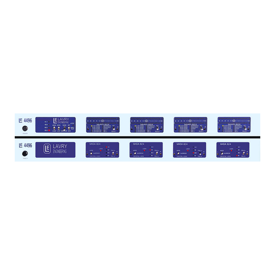
4496 chassis. This flexible design means that the Lavry Blue chassis can be configured to accommodate anything from a single module for stereo AD or DA conversion, to a maximum of eight channels of conversion. The unit may be configured for any mix of functions- for example: 2 channels of AD and 2 channels of DA, or 6 channels of AD plus 2 channels of DA. -
Page 6: M•Sync Multi-Channel Sync Module
4496. If there are no M•AD-824’s in your 4496, there will not be an M•SYNC. In this case, a LAVRY ENGINEERING logo panel takes the place of the M•SYNC panel. For A-to D Clocking Modes, there are three options: -For Internal Clock operation set the far right switch on the MSYNC to INT. - Page 7 LavryBlue 4496 Operation B.) M•SYNC OPERATION INTERNAL CLOCK OPERATION: Set the right-hand switch on LavryBlue M•SYNC to “INT.” The Narrow/Wide switch has no effect when the M•SYNC is set to “Internal” operation. The “Lock" lamp does not illuminate during Internal Clock operation. The 2 left switches set the sample frequency for Internal Clock and External Clock Narrow Mode.
- Page 8 LavryBlue 4496 Operation (External Clock Operation-cont.) -There is a 2X SWITCH on the rear panel near the BNC connectors. Set the 2X SWITCH to “ON” and the M•SYNC’s HIGH/LOW switch to “HIGH” to enable the unit to receive standard sync rates while facilitating conversion at double speed.
-
Page 9: B) Operation
LavryBlue 4496 Operation M•AD-824 Analog to Digital Converter A.) M•AD-824 OPERATION The M•AD-824 is a two-channel unit, converting analog audio to AES digital output in wordlengths of 16, 20, or 24 bits. It receives its clock (internal or external) from the M•SYNC board (multi channel sync). All M•AD-824 units in a 4496 frame receive the same clock signal from the M•SYNC to minimize jitter and inter-channel timing differences. - Page 10 LavryBlue 4496 Operation 1.) USING THE “SET/SELECT” SWITCH ON THE M●AD-824 The SET/SELECT switch is intuitive and actually far easier to use than to describe! Use it to enter (or exit) the Program Mode by holding the switch either up or down for 3 seconds. There are individual functions (Saturation Modes, Reference, &...
- Page 11 LavryBlue 4496 Operation 5.) SELECT DITHER & OPTIONAL NOISE SHAPING for 16bit or 20 bit modes. Dither, ABC-1 and ABC-2 are grouped together (similar to Word Length). • αcoustic βit Correction™ is dither plus psycho-acoustic enhancement of the converter’s dynamic range for word length reduction to 20 or 16 bits. (Some describe this as getting more than 16 bits performance with a 16 bit word length.) •...
- Page 12 LavryBlue 4496 Operation 9.) MASTER-SLAVE MODES A module may operate in either master or slave mode. The slaves copy parameters set on the master to their immediate left. A Master module is located in the leftmost chassis position and set to “master” via its internal DIP switch (position 1 set to “ON”).
- Page 13 Jumpers Settings: Balanced Audio Input Configuration: ● Please Note: In order to maintain good noise rejection qualities, Lavry Engineering recommends that you use balanced inputs for unbalanced sources as well. Four jumpers (J1, J2, J3 and J4) are located behind the analog input XLR connectors: Please be sure to leave the jumpers set for balanced operation.
- Page 14 LavryBlue 4496 Operation C.) M•AD-824 Specifications Dynamic Range- (22Hz – 22KHz unweighted) -114dBFS +/- 1dBFS THD+N -(1KHz unweighted), Internal clock or NARROW lock, typical and worst case: -1dBFS -98dBFS typical. -96dBFS worst case. -3dBFS -102dBFS typical, -98dBFS worst case. -10dBFS -109dBFS typical, -107dBFS worst case.
- Page 15 LavryBlue 4496 Operation Digital to Analog Converter M•DA-824 A.) M●DA-824 OPERATION The M•DA-824 is a two-channel module that converts digital audio to analog audio with word-lengths of 16, 20 or 24 bits at sample rates of 44.1, 48, 88.2 or 96 kHz. The M•DA-824 always clocks to the digital audio signal feeding its XLR input*.
- Page 16 LavryBlue 4496 Operation (M•DA-824 Operation cont.) Looking at the back of the 4496, each M•DA-824 module has a group of three XLR connectors. In each group, the LEFT OUTPUT is the right male XLR and the RIGHT OUTPUT is the left male XLR connector.
- Page 17 LavryBlue 4496 Operation POLARITY SWITCH- This switch on the front panel, with positions marked as “Pin 2 +” and “Pin 3 +”, provides the ability to invert the signal polarity. When set to “Pin 2 +”, a increasing value (positive slope) of the digital input’s waveform causes the voltage on Pin 2 of the XLR analog output to increase, and the voltage on Pin 3 to decrease.
- Page 18 Pin 1 for proper cable shield connection. Lavry Engineering does not recommend using Pin 1 as signal return for unbalanced configuration, thus all the jumpers J2-J5 should be on the board in their proper selected position and the shield should be connected on the XLR end of the cable.
-
Page 19: A) Operation
LavryBlue 4496 Operation MICROPHONE PREAMP A.) OPERATION The LavryBlue Microphone Preamplifier is a dual channel “double width” unit. This means that a 4496 frame can hold a total of two MicPre’s or one MicPre and two other modules. One popular configuration is the “2A2D2MicPre,”... -
Page 20: B) Settings
Pin 3 active unbalanced operation would result in the polarity of the output signal being inverted with most microphones. Lavry Engineering would therefore recommend when configuring the output for Unbalanced operation to use the “Pin 2 active” setting, and wiring the cables that plug into the MicPre outputs accordingly. -
Page 21: Opening The 4496
Lavry Engineering is required to perform the installation. There are a number of critical calibrations that are part of this procedure. Field upgrades not performed by Lavry Engineering or an authorized Lavry Dealer may void the warranty. Your dealer can provide assistance or you can contact Lavry Tech Support: techsupport@lavryengineering.com... - Page 22 LavryBlue 4496 Specifications This Page Left Intentionally Blank...
-
Page 23: Warranty
LIMITED WARRANTY Subject to the conditions set forth below, for one year after the original purchase date of the product, Lavry Engineering will repair the product free of charge in the United States in the event of a defect in materials or workmanship.
Need help?
Do you have a question about the LavryBlue LE-4496 and is the answer not in the manual?
Questions and answers