Cisco Catalyst 3560-CX User Manual
Hide thumbs
Also See for Catalyst 3560-CX:
- Product overview (15 pages) ,
- Manual (24 pages) ,
- Manual (27 pages)
Table of Contents
Advertisement
Advertisement
Table of Contents

Subscribe to Our Youtube Channel
Related Manuals for Cisco Catalyst 3560-CX


Summary of Contents for Cisco Catalyst 3560-CX
- Page 1 Catalyst 3560-CX and 2960-CX Switch Hardware Installation Guide First Published: February 05, 2015 Last Modified: June 24, 2015 Americas Headquarters Cisco Systems, Inc. 170 West Tasman Drive San Jose, CA 95134-1706 http://www.cisco.com Tel: 408 526-4000 800 553-NETS (6387) Fax: 408 527-0883...
- Page 2 Cisco and the Cisco logo are trademarks or registered trademarks of Cisco and/or its affiliates in the U.S. and other countries. To view a list of Cisco trademarks, go to this URL: www.cisco.com/go/trademarks . Third-party trademarks mentioned are the property of their respective owners. The use of the word partner does not imply a partnership relationship between Cisco and any other company.
-
Page 3: Table Of Contents
Modes for Port LEDs PoE LED Console LEDs Port LEDs Rear Panel Internal Power Supply Security Slot Auxiliary Power Adapter Management Options Network Configurations Switch Installation C H A P T E R 2 Catalyst 3560-CX and 2960-CX Switch Hardware Installation Guide... - Page 4 Removing an SFP or SFP+ Module 10/100/1000 PoE+ Port Connections 10/100/1000 Port Connections Auto-MDIX Connections Where to Go Next Troubleshooting C H A P T E R 3 Diagnosing Problems Switch POST Results Switch LEDs Switch Connections Catalyst 3560-CX and 2960-CX Switch Hardware Installation Guide...
- Page 5 Configuring the Switch with the CLI-Based Setup Program A P P E N D I X C Accessing the CLI Through Express Setup Accessing the CLI Through the Console Port Connecting the RJ-45 Console Port Catalyst 3560-CX and 2960-CX Switch Hardware Installation Guide...
- Page 6 Installing the Cisco Microsoft Windows XP USB Driver Installing the Cisco Microsoft Windows 2000 USB Driver Installing the Cisco Microsoft Windows Vista and Windows 7 USB Driver Uninstalling the Cisco Microsoft Windows USB Driver Uninstalling the Cisco Microsoft Windows XP and 2000 USB Driver Using the Setup.exe Program...
-
Page 7: Document Conventions
A vertical line, called a pipe, indicates a choice within a set of keywords or arguments. [x | y] Optional alternative keywords are grouped in brackets and separated by vertical bars. Catalyst 3560-CX and 2960-CX Switch Hardware Installation Guide... - Page 8 Use the statement number provided at the end of each warning to locate its translation in the translated safety warnings that accompanied this device. Statement 1071 SAVE THESE INSTRUCTIONS Catalyst 3560-CX and 2960-CX Switch Hardware Installation Guide viii...
-
Page 9: Related Documentation
Obtaining Documentation and Submitting a Service Request For information on obtaining documentation, submitting a service request, and gathering additional information, see the monthly What's New in Cisco Product Documentation, which also lists all new and revised Cisco technical documentation, at: http://www.cisco.com/c/en/us/td/docs/general/whatsnew/whatsnew.html... - Page 10 Preface Obtaining Documentation and Submitting a Service Request Catalyst 3560-CX and 2960-CX Switch Hardware Installation Guide...
-
Page 11: Chapter
C H A P T E R Product Overview The Catalyst 3560-CX and 2960-CX switches are Ethernet switches to which you can connect devices such as Cisco IP Phones, Cisco Wireless Access Points, workstations, and other network devices such as servers, routers, and other switches. -
Page 12: Front Panel
◦ 10/100/1000 PoE+ Note The Catalyst 3560CX-8XPD-S has 6 PoE+ ports and 2 Multigigabit PoE+ ports. • Two 10/100/1000 uplink ports and two SFP or SFP+ module ports depending on the switch model. Catalyst 3560-CX and 2960-CX Switch Hardware Installation Guide... -
Page 13: Catalyst 3560-Cx And 2960-Cx Switch Hardware Installation Guide
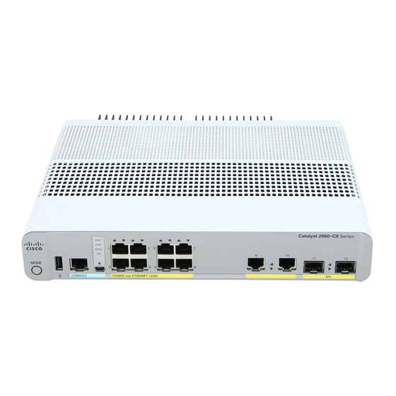
USB mini-Type B (console) port SFP module slots Figure 2: Catalyst 3560CX-8XPD-S Front Panel View Mode button System LEDs USB Type A port 10/100/1000 PoE+ ports RJ-45 console port Multigigabit PoE+ ports Catalyst 3560-CX and 2960-CX Switch Hardware Installation Guide... -
Page 14: Poe And Poe+ Ports
The ports provide PoE+ support for devices compliant with IEEE 802.3af, IEEE 802.3at, and ePoE and also provide Cisco prestandard PoE support for Cisco IP Phones and Cisco Aironet Access Points. The maximum switch power output is either 124 W or 240 W, depending on the switch mode. Intelligent power management allows flexible power allocation across all ports. -
Page 15: Management Ports
• USB mini-Type B console port (5-pin connector). If you use the USB mini-Type B console port, the Cisco Windows USB device driver must be installed on any PC connected to the console port (for operation with Microsoft Windows). Mac OS X or Linux do not require special drivers. -
Page 16: Sfp And Sfp+ Module Slots
The switch has either two 1-Gigabit SFP or 10-Gigabit SFP+ module slots. The slots marked SFP+ support both SFP and SFP+ modules. The SFP slots support only the SFP modules. For Cisco SFP and SFP+ modules documentation, including compatibility matrixes, refer to this URL: http:/ /www.cisco.com/en/US/products/hw/modules/ps5455/products_device_support_tables_list.html... -
Page 17: System Led
• PoE mode is not selected • At least one of the 10/100 or 10/100/100 PoE ports has been denied power • At least one of the ports has a PoE fault Catalyst 3560-CX and 2960-CX Switch Hardware Installation Guide... -
Page 18: Console Leds
Port is blocked by Spanning Tree Protocol (STP) and is not forwarding data. After a port is reconfigured, the port LED is amber for up to 30 seconds as STP searches for loops. Catalyst 3560-CX and 2960-CX Switch Hardware Installation Guide... -
Page 19: Rear Panel
• A loop (for the optional power cord retainer) • Heat sink fins (PoE models only) Figure 5: Rear Panel of a Non-PoE Switch Figure 6: Rear Panel of a PoE Switch Catalyst 3560-CX and 2960-CX Switch Hardware Installation Guide... -
Page 20: Internal Power Supply
Catalyst 3560CX-8PT-S switches can be powered either through the 10/100/1000 uplink ports receiving power from a PoE, PoE+ or UPOE switch or through an auxiliary AC-DC or DC-DC power adapter. You can order Catalyst 3560-CX and 2960-CX Switch Hardware Installation Guide... -
Page 21: Management Options
Cisco Network Assistant is a PC-based network management GUI application for LANs of small and medium-sized businesses. You can use the GUI to configure and manage switch clusters or standalone switches. Cisco Network Assistant is available at no cost and can be downloaded from this URL: http:/ /www.cisco.com/en/US/products/ps5931/index.html... -
Page 22: Network Configurations
• Cisco Prime Infrastructure Cisco Prime Infrastructure combines the wireless functionality of Cisco Prime Network Control System (NCS) and the wired functionality of Cisco Prime LAN Management Solution (LMS), with application performance monitoring and troubleshooting capabilities of Cisco Prime Assurance Manager. For more information, see the Cisco Prime Infrastructure documentation on Cisco.com. -
Page 23: Warnings
This section includes the basic installation caution and warning statements. Read this section before you start the installation procedure. Translations of the warning statements appear in the RCSI guide on Cisco.com. Before working on equipment that is connected to power lines, remove jewelry (including rings, necklaces, Warning and watches). - Page 24 1040 Warning For connections outside the building where the equipment is installed, the following ports must be connected through an approved network termination unit with integral circuit protection: 10/100/1000 Ethernet. Statement 1044 Catalyst 3560-CX and 2960-CX Switch Hardware Installation Guide...
-
Page 25: Box Contents
Obtain these necessary tools and equipment: • Number-2 Phillips screwdriver • Drill with a #27 drill bit (0.144-inch [3.7 mm]) Installation Guidelines When determining where to install the switch, verify that these guidelines are met: Catalyst 3560-CX and 2960-CX Switch Hardware Installation Guide... - Page 26 • For cable requirements for SFP module connections, see the “SFP Module Cables, on page 60” section. Each port must match the wave-length specifications on the other end of the cable, and the cable must not exceed the minimum cable length. Catalyst 3560-CX and 2960-CX Switch Hardware Installation Guide...
-
Page 27: Verifying Switch Operation
If a switch fails POST, the SYST LED turns amber. POST failures are usually fatal. Call Cisco technical support representative if your switch fails POST. After a successful POST, unplug the power cord from the switch and install the switch in a rack, on a wall, on a table, or on a shelf. -
Page 28: On A Desk, Shelf, Or Wall (With Mounting Screws)
Insert two screws in the slots on the screw template, and tighten them until they touch the top of the screw template. Figure 9: Installing the Mounting Screws on Top of a Desk or a Shelf Catalyst 3560-CX and 2960-CX Switch Hardware Installation Guide... -
Page 29: Under A Desk- Or Shelf-Mounting
This ensures that the power cord faces the rear of the desk or shelf after the switch is installed. Wait before you attach the screw template to the desk or shelf. Note Catalyst 3560-CX and 2960-CX Switch Hardware Installation Guide... - Page 30 Step 6 Remove the screw template from underneath the desk or shelf. Step 7 Place the switch upside down onto the mounting screws, and slide it forward until it locks in place. Catalyst 3560-CX and 2960-CX Switch Hardware Installation Guide...
-
Page 31: Wall-Mounting
Position the screw template so that the edge that is marked as CABLE SIDE ENTRY faces toward the floor. For the best support of the switch and cables, make sure that you attach the switch securely to a wall stud or to Note a firmly attached plywood mounting backboard Catalyst 3560-CX and 2960-CX Switch Hardware Installation Guide... - Page 32 Step 6 Insert two screws in the slots on the screw template, and tighten them until they touch the top of the screw template. Figure 13: Installing the Mounting Screws on the Wall Catalyst 3560-CX and 2960-CX Switch Hardware Installation Guide...
-
Page 33: With A Mounting Tray
With a Mounting Tray The mounting kit (part number CMPCT-MGNT-TRAY=) is optional. You can order it when you order your switch, or you can order it later from your Cisco representative. The mounting kit ships contents: • Two number-10 Phillips pan-head screws... -
Page 34: Mounting Tray With Screws
Use a 0.144-in. (3.7 mm) or a #27 drill bit to drill three 1/2-in. (12.7 mm) holes in the desk. Step 3 Insert the three number-8 Phillips pan-head screws in the slots on the mounting tray, and tighten them. Figure 15: Attaching the Tray to the Desk or Shelf Catalyst 3560-CX and 2960-CX Switch Hardware Installation Guide... - Page 35 Use the two number-10 Phillips pan-head screws to secure the switch to the mounting tray. Figure 17: Securing the Switch to the Mounting Tray To prevent airflow restriction, allow clearance around the ventilation openings to be at least: 3 in. (7.6 cm) Statement 1076 Catalyst 3560-CX and 2960-CX Switch Hardware Installation Guide...
-
Page 36: Mounting Tray With A Magnet
This example shows you how to mount the switch on a metal wall. You can use a similar procedure to mount the switch on, or under, a metal desk. Step 1 Place the switch on the mounting tray. Figure 18: Placing the Switch on the Mounting Tray Catalyst 3560-CX and 2960-CX Switch Hardware Installation Guide... - Page 37 Read the wall-mounting instructions carefully before beginning installation. Failure to use the correct hardware or to follow the correct procedures could result in a hazardous situation to people and damage to the system. Statement 378 Catalyst 3560-CX and 2960-CX Switch Hardware Installation Guide...
-
Page 38: In A Rack
Installing the switch in a rack requires an optional bracket kit that is not included with the switch. You can order these kits from your Cisco representative: • 19-inch rack-mounting brackets (RCKMNT-19-CMPCT=) • 23- and 24-inch rack-mounting brackets (RCKMNT-23-CMPCT=) Catalyst 3560-CX and 2960-CX Switch Hardware Installation Guide... - Page 39 Figure 22: Attaching the 23-inch Brackets for Rack-Mounting Insert the switch into the rack and align the bracket in the rack. Use either the number-12 or number-10 Phillips machine screws to secure the switch in the rack. Catalyst 3560-CX and 2960-CX Switch Hardware Installation Guide...
-
Page 40: On A Din Rail
On a DIN Rail The DIN-mount kit (part number CMPCT-DIN-MNT=) is optional. You can order it when you order your switch, or you can order it later from your Cisco representative. The DIN-mount kit contains: • Two number-10 Phillips pan-head screws •... -
Page 41: Attaching The Din-Mount Tray To The Switch
On a DIN Rail Attaching the DIN-Mount Tray to the Switch Step 1 Place the switch on the DIN rail mount. Figure 24: Placing the Switch on the DIN-Mount Tray Switch DIN rail mount Catalyst 3560-CX and 2960-CX Switch Hardware Installation Guide... -
Page 42: Mounting The Switch On A Din Rail
Do not install the switch with its front panel facing up. Following safety regulations, install the switch Caution with its front panel facing down, to allow sufficient airflow and to provide easier access to the cables. Catalyst 3560-CX and 2960-CX Switch Hardware Installation Guide... - Page 43 Rotate the switch down toward the DIN rail until the release tabs on the DIN rail mount clicks. Step 3 Lift lightly on the bottom of the switch to ensure that it is firmly locked in place. Catalyst 3560-CX and 2960-CX Switch Hardware Installation Guide...
-
Page 44: Removing The Switch From A Din Rail
Ensure that power is removed from the switch, and disconnect all cables and connectors from the front panel of the switch. Step 2 Pull down on the DIN rail mount release tabs. As the clips release, lift the bottom of the switch. Figure 27: Switch Removal Catalyst 3560-CX and 2960-CX Switch Hardware Installation Guide... -
Page 45: Attaching The Adapter Bracket To The Switch (Optional)
Insert the 3 tabs of the power adapter bracket into the corresponding 3 slots on the rear side of the mounting tray or DIN rail mount. Figure 28: Inserting the power adapter bracket in to the mounting tray or DIN rail mount Catalyst 3560-CX and 2960-CX Switch Hardware Installation Guide... -
Page 46: Installing The Power Cord Retainer (Optional)
Note The power cord retainer part number (PWR-CLP=) is optional. You can order it when you order your switch, or you can order it later from your Cisco representative. Step 1 Choose the sleeve size of the power cord retainer based on the thickness of the cord. The smaller sleeve can be snapped off and used for thin cords. - Page 47 Sleeve for thinner power cords Power cord retainer Loop Step 3 Slide the retainer through the first latch. Figure 31: Sliding the Retainer Through the Latch AC power cord Latch Smaller sleeve for thin power cords Catalyst 3560-CX and 2960-CX Switch Hardware Installation Guide...
- Page 48 (Optional) Use the small sleeve for thin power cords. Use the small sleeve to provide greater stability for thin cords. Detach the sleeve, and slide it over the power cord. Figure 33: Sleeve Around the Power Cord Smaller sleeve for thin power cords AC power cord Catalyst 3560-CX and 2960-CX Switch Hardware Installation Guide...
-
Page 49: Installing The Cable Guard (Optional)
The cable guard prevents tampering with the cables after the cables are installed. The cable guard (CMPCT-CBLE-GRD=) is not included with the switch, but you can order it from your Cisco representative. You can use the cable guard when the switch is mounted on a desk, under a desk, or on a wall. - Page 50 Step 2 Use the supplied number-10 pan-head screws to attach the cable guard to the switch. Figure 36: Attaching the Cable Guard to the Switch Switch Two number-10 Phillips pan-head screws Cable Guard Catalyst 3560-CX and 2960-CX Switch Hardware Installation Guide...
- Page 51 Figure 37: Pivoting the Cable Guard Upwards Cable guard Pivot direction for cable guard pivots Step 4 Attach the cables to the switch. Figure 38: Attaching the Cables to the Switch Cables Pivot direction for cable guard pivots Catalyst 3560-CX and 2960-CX Switch Hardware Installation Guide...
- Page 52 (12.7 mm) holes at each of the two mounting locations. Insert the supplied 0.5 in. (12.7 mm) number-8 Phillips wood screws and tighten them. Figure 40: Securing the Cable Guard to the Desk Number-8 Phillips wood screws Desk or shelf Catalyst 3560-CX and 2960-CX Switch Hardware Installation Guide...
-
Page 53: Installing Sfp And Sfp+ Modules
The SFP+ slots support both SFP and SFP+ modules. See the switch release notes on Cisco.com for the list of supported SFP modules. Use only Cisco SFP modules on the switch. Each Cisco module has an internal serial EEPROM that is encoded with security information. -
Page 54: Removing An Sfp Or Sfp+ Module
5. Grasp the SFP or SFP+ module, and carefully remove it from the module slot. 6. Place the module in an antistatic bag or other protective environment. Catalyst 3560-CX and 2960-CX Switch Hardware Installation Guide... -
Page 55: 10/100/1000 Poe+ Port Connections
On a per-port basis, you can control whether or not a port automatically provides power when an IP phone or an access point is connected. To access an advanced PoE planning tool, use the Cisco Power Calculator available on Cisco.com at this URL: http://tools.cisco.com/cpc/launch.jsp... -
Page 56: 10/100/1000 Port Connections
Repeat Steps 1 through 3 to connect each device. Note Many legacy powered devices, including older Cisco IP phones and access points that do not fully support IEEE 802.3af, might not support PoE when connected to the switches by a crossover cable. -
Page 57: Where To Go Next
GUI, you can configure and monitor a switch cluster or an individual switch. • Use the CLI to configure the switch as a member of a cluster or as an individual switch from the console. • Use the Cisco Prime Infrastructure application. Catalyst 3560-CX and 2960-CX Switch Hardware Installation Guide... - Page 58 Switch Installation Where to Go Next Catalyst 3560-CX and 2960-CX Switch Hardware Installation Guide...
-
Page 59: Troubleshooting
You can also get statistics from Device Manager, from the CLI, or from an SNMP workstation. Switch POST Results POST failures are usually fatal. Contact your Cisco technical support representative if your switch does Note not pass POST. -
Page 60: Switch Connections
• Verify that you are using the correct cable type. • Look for loose connections. Sometimes a cable appears to be seated, but is not. Disconnect the cable and then reconnect it. Catalyst 3560-CX and 2960-CX Switch Hardware Installation Guide... -
Page 61: 10/100/1000 Port Connections
SFP and SFP+ Module Use only Cisco SFP or SFP+ modules in the switch. Each Cisco module has an internal serial EEPROM that is encoded with security information. This encoding provides a way for Cisco to identify and validate that the module meets the requirements for the switch. -
Page 62: Interface Settings
Problems sometimes occur between the switch and third-party network interface cards (NICs). By default, the switch ports and interfaces autonegotiate. Laptops or other devices are commonly set to autonegotiate, yet sometimes autonegotiation issues occur. Catalyst 3560-CX and 2960-CX Switch Hardware Installation Guide... -
Page 63: Cabling Distance
At the switch prompt, enter enable, and press Return or Enter. Step 2 At the Privileged EXEC prompt, , enter setup and press Return or Enter. switch# The switch displays the prompt to run the initial configuration dialog. Catalyst 3560-CX and 2960-CX Switch Hardware Installation Guide... -
Page 64: Finding The Switch Serial Number
Finding the Switch Serial Number Finding the Switch Serial Number If you contact Cisco Technical Assistance, you need to know the switch serial number. You can also use the show version privileged EXEC command to see the switch serial number. -
Page 65: Appendix A Technical Specifications
-22 to 158°F (-30 to 70°C) up to 15,000 ft (4573 m) Relative humidity 5 to 95% (noncondensing) Operating altitude Up to 10,000 ft (3000 m) Storage altitude Up to 15,000 ft (4500 m) Physical Specifications Weight Catalyst 3560CX-8PC-S 5.0 lb (2.27 kg) Catalyst 3560-CX and 2960-CX Switch Hardware Installation Guide... -
Page 66: Power Requirements
1.75 x 10.6 x 10.4 (4.44 x 26.9 x 26.4 cm) Power Requirements AC Input Voltage - 100 to 240 VAC (autoranging) Catalyst 3560CX-8PC-S 100-240 VAC, 50-60 Hz, 3.25-1.5A Catalyst 3560CX-8TC-S 100-240 VAC, 50-60 Hz, 0.5-0.2A Catalyst 3560-CX and 2960-CX Switch Hardware Installation Guide... - Page 67 1057.7 Catalyst 3560CX-8PT-S 375.3 Catalyst 3560CX-8XPD-S 1057.7 Power Rating BTUs per Hour Catalyst 3560CX-8PC-S 0.3 KVA Catalyst 3560CX-8TC-S 0.05 KVA Catalyst 2960CX-8PC-L 0.3 KVA Catalyst 2960CX-8TC-L 0.05 KVA Catalyst 3560CX-12PC-S 0.3 KVA Catalyst 3560-CX and 2960-CX Switch Hardware Installation Guide...
-
Page 68: Poe Power Consumption
Catalyst 3560CX-8TC-S 19.7W Catalyst 27.8W 253.0W 240W 3560CX-12PC-S Catalyst 21.9W 3560CX-12TC-S Catalyst 32.6W 254.7W 240W 3560CX-12PD-S Catalyst 2960CX-8PC-L 24.5W 135.5W 1 24W Catalyst 2960CX-8TC-L 20.0W Catalyst 3560CX-8PT-S Up to 146W Catalyst 240W 3560CX-8XPD-S Catalyst 3560-CX and 2960-CX Switch Hardware Installation Guide... -
Page 69: Appendix B Connector And Cable Specifications
• Connector Specifications, page 59 • Cables and Adapters, page 60 Connector Specifications 10/100/1000 Ports (Including PoE) All 10/100/1000 ports use standard RJ-45 connectors and Ethernet pinouts. Figure 43: 10/100/1000 Port Pinouts Catalyst 3560-CX and 2960-CX Switch Hardware Installation Guide... -
Page 70: Sfp Module Connectors
Figure 45: Simplex LC Cable Connector Figure 46: Copper SFP Module LC Connector Cables and Adapters SFP Module Cables For cabling specifications, refer to the Cisco SFP and SFP+ Transceiver Module Installation Notes. Catalyst 3560-CX and 2960-CX Switch Hardware Installation Guide... - Page 71 Each port must match the wave-length specifications on the other end of the cable, and the cable must not exceed the stipulated cable length. Copper 1000BASE-T SFP module transceivers use standard four twisted-pair, Category 5 cable at lengths up to 328 feet (100 meters). Catalyst 3560-CX and 2960-CX Switch Hardware Installation Guide...
-
Page 72: Cable Pinouts
Cable Pinouts Cable Pinouts Figure 47: Four Twisted-Pair Straight-Through Cable Schematic Figure 48: Four Twisted-Pair Semi-Cross Cable Schematic Figure 49: Two Twisted-Pair Straight-Through Cable Schematic Figure 50: Two Twisted-Pair Crossover Cable Schematic Catalyst 3560-CX and 2960-CX Switch Hardware Installation Guide... -
Page 73: Console Port Adapter Pinouts
PC. You need to provide a RJ-45-to-DB-25 female DTE adapter to connect the switch console port to a terminal. You can order the kit (part number ACS-DSBUASYN=) from Cisco. Table 3: Console Port Signaling with a DB-9 Adapter... - Page 74 Switch Console Port (DTE) RJ-45-to-DB-9 Terminal Adapter Console Device Signal DB-9 Pin Signal Table 4: Console Port Signaling with a DB-25 Adapter Switch Console Port (DTE) RJ-45-to-DB-25 Terminal Adapter Console Device Signal DB-25 Pin Signal Catalyst 3560-CX and 2960-CX Switch Hardware Installation Guide...
-
Page 75: Appendix C Configuring The Switch With The Cli-Based Setup Program
You can access the CLI on a configured or unconfigured switch by connecting the RJ-45 console port or USB console port of the switch to your PC or workstation and accessing the switch through a terminal emulation program. Catalyst 3560-CX and 2960-CX Switch Hardware Installation Guide... -
Page 76: Connecting The Rj-45 Console Port
Power on the switch as described in the switch getting started guide. Step 5 The PC or terminal displays the bootloader sequence. Press Enter to display the setup prompt. Follow the steps in Entering the Initial Configuration Information, on page Catalyst 3560-CX and 2960-CX Switch Hardware Installation Guide... -
Page 77: Connecting The Usb Console Port
1. If you are connecting the switch USB console port to a Windows-based PC for the first time, install the USB driver. See Installing the Cisco Microsoft Windows USB Device Driver, on page 2. Connect a USB cable to the PC USB port. Connect the other end of the cable to the switch mini-B (5-pin-connector) USB console port. - Page 78 If you are connecting the switch USB console port to a Windows-based PC for the first time, install the USB driver. See Installing the Cisco Microsoft Windows USB Device Driver, on page Figure 52: Connecting the USB Console Cable to the Switch...
-
Page 79: Installing The Cisco Microsoft Windows Usb Device Driver
Installing the Cisco Microsoft Windows XP USB Driver SUMMARY STEPS 1. Obtain the Cisco USB console driver file from the Cisco.com web site and unzip it. 2. If using 32-bit Windows XP, double-click the setup.exe file in the Windows_32 folder. If using 64-bit Windows XP, double-click the setup(x64).exe file in the Windows_64 folder. -
Page 80: Installing The Cisco Microsoft Windows 2000 Usb Driver
Installing the Cisco Microsoft Windows 2000 USB Driver SUMMARY STEPS 1. Obtain the Cisco USB console driver file from the Cisco.com web site and unzip it. 2. Double-click the setup.exe file. 3. The Cisco Virtual Com InstallShield Wizard begins. Click Next. -
Page 81: Installing The Cisco Microsoft Windows Vista And Windows 7 Usb Driver
Installing the Cisco Microsoft Windows Vista and Windows 7 USB Driver SUMMARY STEPS 1. Obtain the Cisco USB console driver file from the Cisco.com web site and unzip it. 2. If using 32-bit Windows Vista or Windows 7, double-click the setup.exe file in the Windows_32 folder. -
Page 82: Using The Add Or Remove Programs Utility
SUMMARY STEPS 1. Run setup.exe for Windows 32-bit or setup(x64).exe for Windows-64bit. Click Next. 2. The InstallShield Wizard for Cisco Virtual Com appears. Click Next. 3. When the Program Maintenance window appears, select the Remove radio button. Click Next. 4. When the Remove the Program window appears, click Remove. -
Page 83: Entering The Initial Configuration Information
SUMMARY STEPS 1. Run setup.exe for Windows 32-bit or setup(x64).exe for Windows-64bit. Click Next. 2. The InstallShield Wizard for Cisco Virtual Com appears. Click Next. 3. When the Program Maintenance window appears, select the Remove radio button. Click Next. 4. When the Remove the Program window appears, click Remove. -
Page 84: Completing The Setup Program
Would you like to enter basic management setup? [yes/no]: yes Step 2 Enter a host name for the switch, and press Return. Catalyst 3560-CX and 2960-CX Switch Hardware Installation Guide... - Page 85 Configure the interface by entering the switch IP address and subnet mask and pressing Return. The IP address and subnet masks shown are examples. Configuring interface vlan1: Configure IP on this interface? [yes]: yes IP address for this interface: 10.4.120.106 Subnet mask for this interface [255.0.0.0]: 255.0.0.0 Catalyst 3560-CX and 2960-CX Switch Hardware Installation Guide...
- Page 86 [1] Return back to the setup without saving this config. [2] Save this configuration to nvram and exit. Choose (2) to save the configuration to NVRAM to use it the next time the switch reboots. Enter your selection [2]:2 Catalyst 3560-CX and 2960-CX Switch Hardware Installation Guide...
- Page 87 Configuring the Switch with the CLI-Based Setup Program Completing the Setup Program The switch now runs this default configuration. If you want to change this configuration or perform other management tasks, see Management Options, on page Catalyst 3560-CX and 2960-CX Switch Hardware Installation Guide...
- Page 88 Configuring the Switch with the CLI-Based Setup Program Completing the Setup Program Catalyst 3560-CX and 2960-CX Switch Hardware Installation Guide...
Need help?
Do you have a question about the Catalyst 3560-CX and is the answer not in the manual?
Questions and answers