
Related Manuals for Aphex PROJECT 500


Summary of Contents for Aphex PROJECT 500
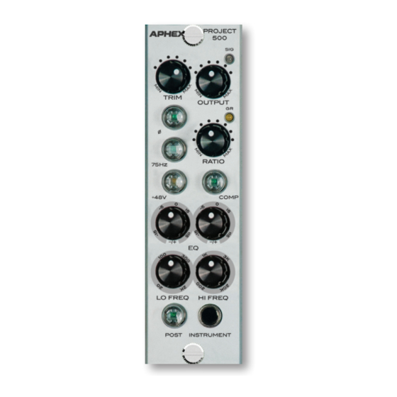
- Page 1 PROJECT 500 ™ CLASS A MIC PRE, OPTICAL COMPRESSOR, DUAL BAND EQ 500 SERIES CHANNEL STRIP MODULE Owner’s Manual...
- Page 2 WARNING: The PROJECT 500 has been tested and meets the FCC, CE and European Union rules, regulations, and guidelines for use. Do not attempt to modify or change the PROJECT 500, as this could void the regulatory compliance, which would place you at risk of losing your authority to operate the PROJECT 500.
- Page 3 SAFETY DECLARATIONS This equipment has been tested and found to comply with the limits for a Class B digital device, pursuant to part 15 of the FCC rules. These limits are designed to provide reasonable protection against harmful interference in a residential installation. This equipment generates, uses and can radiate radio frequency energy and, if not installed and used in accordance with the instructions, may cause harmful interference to radio communications.
-
Page 4: Table Of Contents
TABLE OF CONTENTS 1.0 INSTALLATION 2.0 INTRODUCTION 3.0 CONTROLS & INDICATORS 3.1 Trim Control 3.2 Compressor On/Off Button 3.3 Gain Reduction LED 3.4 Ratio Control 3.5 Post Button 3.6 Cut/Boost Knobs 3.7 Frequency Knobs 3.8 Output Knob 3.9 Phase Reverse Button 3.10 High Pass Filter 3.11 Phantom Power Button 3.12 Instrument Input... -
Page 5: Installation
500 series rack. 3. Pull your Project 500 module out of its box and carefully slide it into place in the designated opening. Sight down the back of the module (use a flashlight if necessary) and ensure the card edge connector is aligned to seat into the card slot of the frame. -
Page 6: Introduction
2.0 INTRODUCTION The Project 500 is a 500 Series channel strip module that includes a Class-A mic pre, an optical compressor and a two-band equal- izer. The optocoupler was designed to be as fast as possible and is produced exclusively for Aphex. The inputs and outputs are elec- tronically balanced. -
Page 7: Gain Reduction Led
3.3 GAIN REDUCTION LED The Gain Reduction LED provides visual feed- back as to the amount of gain reduction. The LED will glow yellow when gain reduction occurs. The brighter it glows, the more gain reduction is taking place. 3.4 RATIO CONTROL The Ratio knob controls the decibel relation- ship between the amount of increase in input signal vs. -
Page 8: Cut/Boost Knobs
EQUALIZER CONTROLS 3.6 CUT/BOOST KNOBS Each EQ band can be cut or boosted by 15dB. 3.7 FREQUENCY KNOBS The low frequency band knob allows set- tings from 20Hz to 2kHz. The high frequency band knob allows set- tings from 1kHz to 20kHz. 3.8 OUTPUT KNOB The Output level knob determines the over- all output level of the module. -
Page 9: Service & Warranty
EXCLUSION OF CERTAIN DAMAGES Aphex’s liability for any defective unit is limited to the repair or replacement of said unit, at our option, and shall not include damages of any other kind, whether incidental, consequential, or otherwise. -
Page 10: Service Information
4.2 SERVICE INFORMATION If it becomes necessary to return this unit for repair, you must first contact Aphex for a Return Authorization (RMA number), which will need to be included with your shipment for proper identification. If available, repack this unit in its original carton and packing material. Otherwise, pack the equipment in a strong carton containing at least 2 inches of padding on all sides. - Page 11 Page 11...
- Page 12 PO Box 711674 Salt Lake City, Utah 84171 USA PHONE: 801.699.2272 FAX: 435.604.7409 www.APHEX.com Page 12...
Need help?
Do you have a question about the PROJECT 500 and is the answer not in the manual?
Questions and answers