Table of Contents
Advertisement
Quick Links
Advertisement
Table of Contents

Related Manuals for Legacy Harmony


Summary of Contents for Legacy Harmony
- Page 1 Owners Manual For The Harmony Loudspeaker System...
-
Page 2: Table Of Contents
Table of Contents Page Registration Owners Record The Cabinetry / Our Commitment Setup Unpacking Your Speakers Speaker Installation 6-16 Hooking Up Cables 17-19 Amplification 20-22 Technology Designer’s Note Specifications... -
Page 3: Owners Record
Refer to this when calling your dealer regarding this product. Model: Harmony HD Serial No: _________________________ Date of purchase: ___________________ Thank you for selecting a Legacy Loudspeaker System. These hand- crafted instruments will provide you with many years of listening en- joyment. -
Page 4: The Cabinetry / Our Commitment
Our Commitment A great deal of forethought, love and satisfaction is instilled in each piece of Legacy workmanship. We take pride in getting to know many of our customers on a first name basis. Your purchase of this product is backed by the renowned “Legacy... -
Page 5: Unpacking Your Speakers
V-board corner protectors. Molded foam end caps are used to protect the elegant cabinetry, and a plastic liner is provided as waterproofing. Please save this packing for future transportation. If cartons become damaged or misplaced, new ones can be purchased from Legacy Audio. -
Page 6: Speaker Installation
WARNING: Wear Eye Protection when cutting drywall. Also be certain there are no electrical, water, heating, or gas lines inside the wall in the location you plan to mount your Harmony loudspeakers. - Page 7 Speaker Installation Installing the Harmony In-Wall Loudspeakers Packing List Harmony Speaker Installation Manual (2) Support Blocks (4) Support Block Screws (2) Tensioning Screws Tools Required Pencil Drywall Saw Level Phillips Screwdriver Tape Measure Mallet...
- Page 8 Due to Harmony’s unique patented design, Installation is identical for new or existing construc- tion. The Harmony speaker is designed to perform at its best when the bottom of the speaker is located well off the floor (about 2.5 feet). While it may be installed at greater heights, it will per- form most optimally if the variance is kept within 6”...
- Page 9 Speaker Installation Cut Opening - Locate the mounting area between two studs. - Using a level, scribe two 14.5” horizontal guide lines onto wall surface. The upper line should be 70” off the floor. The lower line is 30.75” off the floor. (Figure 2)
- Page 10 Speaker Installation - Using a drywall saw, cut out the wall opening for the Harmony speaker. The inward facing edges of the studs will serve as vertical guides for the saw. When cut properly, an opening approximately 39.25” x 14.5” will result. (Figure 3) WARNING: Wear eye protection when cutting dry wall.
- Page 11 Speaker Installation Mount Isolating Support Blocks - Position the first of two support blocks as shown. (Figure 4) - With a pencil, scribe a horizontal line onto the stud at a distance 12.75” down from the top. - Hold the top of the block even with the scribed line. - Slide the block until it protrudes 0.75”...
- Page 12 Speaker Installation...
- Page 13 - Strip and terminate speaker cable with spade lugs, banana plugs or twisted bare wire. (Figure 8) - Connect each Harmony to the appropriate +, - output terminals of your amplifier or receiver. Harmony should not be connected in parallel with another speaker to...
- Page 14 Speaker Installation - With Harmony cabinet setting on floor, or elevated onto a soft chair, connect positive and negative speaker wire leads to corresponding red and black terminals on bottom of cabinet. (Figure 9)
- Page 15 Speaker Installation - With assistance, slide a Harmony speaker cabinet onto iso lating support blocks as shown. (Figure 10) - Install provided tensioning screws through isolation grom met as shown. (Note: Though the screw couples directly into the end of the support block, the internal steel plate isolation grommet prevent direct mechanical coupling.)
-
Page 16: Speaker Installation
Speaker Installation... -
Page 17: Hooking Up Cables
Hooking Up Cables Before you purchase loudspeaker wire, check local building codes to make sure that the wire is rated to comply with applicable local safety codes such as UL or CL-2. Use only stranded wire no thinner than AWG 16. For runs longer than 100 feet, we recommend mini- mum of AWG 14. - Page 18 Hooking Up Cables The ideal conductor would have negligible resistance, inductance and capacitance. The table below shows how a few actual speaker cables measure up. Cable s/ft pF/ft µH/ft 12 ga. 0.0033 0.21 14 ga. 0.0048 0.13 16 ga. 0.0079 0.18 18 ga.
-
Page 19: Hooking Up Cables
Hooking Up Cables What about phase shift due to frequency dependent travel times down the speaker cable? Measurements show that 100 Hz waves will be delayed about 20 billionths of a second behind 10 kHz waves when traveling to the end of a 10 foot speaker cable. Since the cilia of the ear requires 25,000 times longer than this just to transmit phase information, phase shifting is obviously not the primary concern when considering speaker cables. -
Page 20: Amplification
For this reason, extensive measures have been taken to ensure that each Legacy speaker system represents a smooth, non-reactive load to virtually any amplifier. Often there is much confusion regarding amplification and loudness levels. It should be under- stood that the role of the amplifier goes beyond that of driving loudspeakers to a given sound pressure level. - Page 21 Some audiophiles feel that 200 watts per channel is the bare minimum to avoid audible clipping distortion when reproducing music at “live” playback levels. Your Legacy speakers are designed to take advan- tage of “high-powered” amplifiers, so don’t be afraid to put them through their paces.
- Page 22 Amplification When an amplifier is unable to fulfill your loudspeakers demands, a damaging harmonic spike may be leaked to the high frequency drivers. Another important point regarding loudness is that the dB scale is a logarithmic one. This means that a 150 Watt amplifier will potentially sound only twice as loud as a 15 Watt amplifier.
-
Page 23: Designer's Note
Designer’s Note (From Bill Dudleston) Harmony In-Walls were developed using the finest loud speaker and crossover components available. Countless hours of computer modeling were spent to insure accurate audio reproduction in a variety of installations where placement compromises must sometimes be made. The... -
Page 24: Specifications
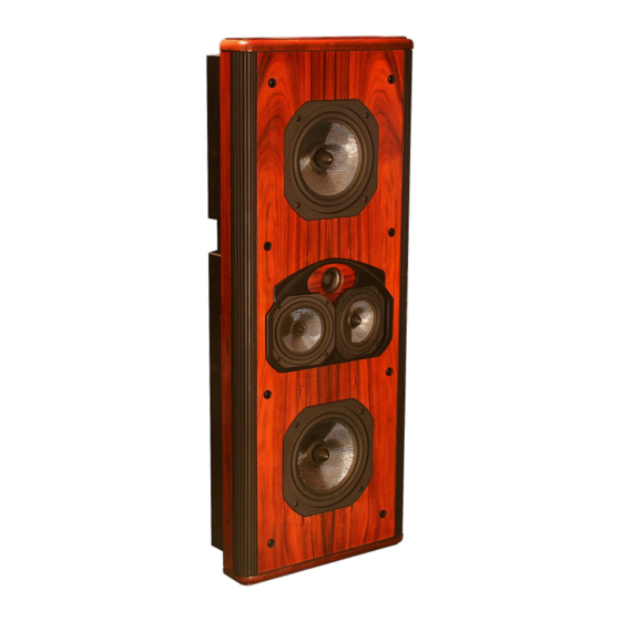
Specifications System Type: 5 drivers, 3 way Tweeter: 1” Silk Dual Diaphragm W/ Quadra-Pole Neodymium Motor Midwoofer: 2 x 5.25” Silver Graphite Woofer: 2 x 8” Silver Graphite Low Frequency Alignment: 3rd Order Assisted Frequency Response: 49Hz – 25 kHz Impedance: 4 Ohms Sensitivity:... - Page 25 Notes:...
- Page 26 ©2008 Legacy Audio 3023 E Sangamon Ave. Springfield, IL 62702 Phone: 800-283-4644 Fax: 217-544-1483...
Need help?
Do you have a question about the Harmony and is the answer not in the manual?
Questions and answers