Table of Contents
Advertisement
Quick Links
Advertisement
Table of Contents

Subscribe to Our Youtube Channel
Related Manuals for Fiat 2014 500e


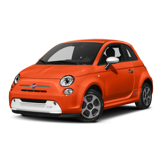
Summary of Contents for Fiat 2014 500e
- Page 1 2 0 14 U S E R GU I D E...
- Page 2 We hope you find it useful. Replacement DVD kits may be purchased by visiting www.techauthority.com. FIAT is a registered trademark of FIAT Group Marketing & Corporate Communication S.p.A, used under license by Chrysler Group LLC. Copyright 2014 Chrysler Group LLC.
-
Page 3: Table Of Contents
TABLE OF CONTENTS INTRODUCTION/WELCOME UTILITY WELCOME FROM FIAT ....2 TRAILER TOWING WEIGHTS IMPORTANT VEHICLE INFORMATION ..4 (MAXIMUM TRAILER WEIGHT RATINGS) ..55... -
Page 4: Introduction/Welcome
INTRODUCTION/WELCOME WELCOME FROM FIAT Congratulations on selecting your new FIAT 500e. Be assured that your 500e represents an elegant marriage of technology and Italian styling that is as good for the environment as is fun to drive! Your new 500e has characteristics to enhance the driver's control under some driving conditions. - Page 5 INTRODUCTION/WELCOME WARNING! • Pedals that cannot move freely can cause loss of vehicle control and increase the risk of serious personal injury. • Always make sure that objects cannot fall into the driver foot well while the ve- hicle is moving. Objects can become trapped under the brake pedal and accelera- tor pedal causing a loss of vehicle control.
-
Page 6: Important Vehicle Information
INTRODUCTION/WELCOME IMPORTANT VEHICLE INFORMATION • Your 500e operates entirely on electricity stored in the high voltage battery. Unlike a conventional vehicle or Hybrid there is no internal combustion engine. Battery Electric Vehicles have unique operating characteristics that you should become familiar with to ensure you are getting the optimal performance from your vehicle. - Page 7 INTRODUCTION/WELCOME High Voltage Battery Service Disconnect • The high voltage battery service disconnect is located under the rear passenger seat lower cushion. If your vehicle requires service see your authorized dealer. WARNING! Never try to remove the high voltage service disconnect. The high voltage service dis- connect is used when your vehicle requires service by a trained technician at an autho- rized dealer.
-
Page 8: Controls At A Glance
CONTROLS AT A GLANCE DRIVER COCKPIT 1. BLUE & ME™ Hands-Free Communication Switches pg. 45 2. Turn Signal/Lights Lever (behind steering wheel) pg. 34 3. Battery Gauge pg. 16 4. Instrument Cluster pg. 8 5. Electronic Vehicle Information Center (EVIC) Display pg. 51 6. - Page 9 CONTROLS AT A GLANCE 12. Audio System pg. 42 13. Glove Box 14. Climate Control pg. 39 15. Shift Buttons 16. Climate Controls Automatic Operation pg. 39 17. Power Windows pg. 39 18. Hood Release pg. 72 19. Tilt Steering Wheel pg. 32 20.
-
Page 10: Instrument Cluster
CONTROLS AT A GLANCE INSTRUMENT CLUSTER 1. Speedometer 2. Battery Usage 3. Messages, Blue & Me and Interface Options 4. Range Projection Indicators Warning Lights - Electric Vehicle System - Seat Belt Reminder Light Warning Light - Power Steering System - Regenerative Brake System Warning Light Warning Light... - Page 11 CONTROLS AT A GLANCE 5. Drive Mode Indicator 6. Driver Behavior Gauge 7. Driving Range Indicators - Turn Signal Indicators - High Beam Indicator - Front Fog Light Indicator - Park/Headlight ON Indicator - Electronic Speed Control SET Indicator - Door Ajar Indicator - Electronic Stability Control (ESC) OFF Indicator - Electronic Stability Control (ESC) Indicator...
-
Page 12: Getting Started
GETTING STARTED ELECTRIC VEHICLE FEATURES Auto Park • The Auto Park feature automatically places the vehicle into PARK if there is any indica- tion that the driver may leave the vehicle while the drive mode indicator is in the D (DRIVE), N (NEUTRAL) or R (REVERSE) modes. •... -
Page 13: Smartphone Features
GETTING STARTED Smartphone Features With the “FIAT Access” smartphone app, you can monitor the state of charge of the high voltage battery or initiate charging from your phone. You can also turn on your car’ s cli- mate control system remotely. The smartphone app provides the following features: •... - Page 14 GETTING STARTED 2. Scroll down and select “Connectivity ID”. After obtaining the connectivity ID and VIN number return to the vehicle registration website and perform the following: 1. After entering the VIN (Vehicle Identification Number), Connectivity ID and your email address, click “submit”. 2.
-
Page 15: Electric System Operation
GETTING STARTED ELECTRIC SYSTEM OPERATION Level 1 Charging (120V — Requires NEMA 5–15 Outlet) • Level 1 charging is done by using a conventional 120 Volt AC (Alternating Current) grounded receptacle along with the NEMA 5–15 Electric Vehicle Supply Equipment (EVSE) that comes standard with your vehicle. - Page 16 GETTING STARTED EVSE Operation And Status Information Indicator Description Green indicates READY 1 — AC Indicator LED RED Indicates a fault Green indicates READY 2 — Fault Indicator LED RED indicates a fault All ON indicates system ready and not charging 3 —...
- Page 17 GETTING STARTED Fault Indicator AC LED Charge Level Indicator LED's • • • • • • • After the EVSE is connected to the vehicle's charge inlet the EVSE will continue to illuminate all LED's green. • Once the vehicle begins charging the EVSE Charge level LED's will illuminate in order from left to right, then shut off.
-
Page 18: Charging The High Voltage Battery
GETTING STARTED CHARGING THE HIGH VOLTAGE BATTERY 1. Put the vehicle in PARK. 2. Turn the ignition to the OFF position. 3. Remove the Level 1 EVSE from its storage bin by lifting the rear cargo cover. 4. Uncoil the entire length of the EVSE (charge cord). - Page 19 GETTING STARTED 7. Plug the EVSE into the charge receptacle. Push the EVSE in firmly until it is completely engaged (if not completely engaged the vehicle may not charge). NOTE: • The vehicle will initiate the charging cycle automatically when all the condi- tions are satisfied.
- Page 20 GETTING STARTED Instrument Panel State Of Charge Indicator • In addition to the instrument cluster the vehicle is also equipped with a State Of Charge indicator. The indicator is made up of five lights that are mounted to the center of the instrument panel. •...
-
Page 21: Starting Your 500E
GETTING STARTED STARTING YOUR 500e • Before starting your vehicle, adjust your seat, adjust both inside and outside mirrors, and fasten your seat belts. WARNING! • Never leave children alone in a vehicle, or with access to an unlocked vehicle. •... -
Page 22: Key Fob
GETTING STARTED KEY FOB Locking And Unlocking The Doors And Liftgate • Press the LOCK button on the Remote Keyless Entry (RKE) transmitter once to lock all the doors and the liftgate. • Press the UNLOCK button on the Remote Keyless Entry (RKE) transmitter once to unlock the driver’... -
Page 23: Vehicle Security Alarm
GETTING STARTED VEHICLE SECURITY ALARM This Vehicle Security Alarm monitors the doors, liftgate, and ignition switch for unauthor- ized operation. When the alarm is activated, the interior switches for door locks are disabled. The Vehicle Security Alarm provides both audio and visual signals repeatedly for three minutes. If the disturbance is still present (driver's door, passenger door, other doors, ignition) after three minutes, the parking lights and tail lights will flash for an additional 15 minutes. -
Page 24: Supplemental Restraint System (Srs) - Air Bags
GETTING STARTED A frayed or torn belt could rip apart in a collision and leave you with no protection. Inspect the belt system periodically, checking for cuts, frays, or loose parts. Damaged parts must be replaced immediately. Do not disassemble or modify the system. Seat belt assemblies must be replaced after a collision if they have been damaged (bent retractor, torn webbing, etc.). -
Page 25: Child Restraints
GETTING STARTED WARNING! • Relying on the air bags alone could lead to more severe injuries in a collision. The air bags work with your seat belt to restrain you properly. In some collisions, the air bags won't deploy at all. Always wear your seat belts even though you have air bags. - Page 26 GETTING STARTED LATCH — Lower Anchors And Tethers For CHildren • Your vehicle is equipped with the child restraint anchorage system called LATCH, which stands for Lower Anchors and Tethers for CHildren. • All rear seating positions have lower anchors and top tether anchors. •...
- Page 27 GETTING STARTED WARNING! This vehicle does not have a center seating position. Do not use the center lower LATCH anchorages to install a child seat in the center of the back seat. Installing The Child Restraint Using The LATCH Lower Anchors NOTE: Never “share”...
- Page 28 GETTING STARTED 5. Try to pull the webbing out of the retractor. If it is locked, you should not be able to pull out any webbing. If the retractor is not locked, repeat the last step. 6. Finally, pull up on any extra webbing to tighten the lap portion around the child re- straint while you push the child restraint rearward and downward into the vehicle seat.
- Page 29 GETTING STARTED WARNING! • In a collision, an unrestrained child, even a tiny baby, can become a projectile inside the vehicle. The force required to hold even an infant on your lap could become so great that you could not hold the child, no matter how strong you are. The child and others could be severely injured or killed.
-
Page 30: Front Seats
GETTING STARTED FRONT SEATS Manual Seat Adjustment Forward/Rearward • Lift up on the adjusting bar, located at the front of the seat near the floor, and release at the desired position. Then, using body pressure, move forward and backward on the seat to be sure that the seat adjusters have latched. - Page 31 GETTING STARTED Seat Height • Drivers front seat height can be raised or lowered by using a lever, located on the out- board side of the seat. Pump the lever upward to raise the seat height, or pump the lever downward to lower the seat height. Seat Height Lever EZ Entry Seats •...
-
Page 32: Rear Seats
GETTING STARTED WARNING! • Adjusting a seat while the vehicle is moving is dangerous. The sudden movement of the seat could cause you to lose control. The seat belt might not be properly adjusted, and you could be severely injured or killed. Only adjust a seat while the vehicle is parked. -
Page 33: Heated Seats
GETTING STARTED HEATED SEATS Front Heated Seats The heated seat switches are located on the center instrument panel area. • Press the switch once to turn on the heated seat. • Press the switch a second time to turn off the heated seat. Heated Seat Switches WARNING! •... -
Page 34: Tilt Steering
GETTING STARTED TILT STEERING The tilt lever is located on the steering column, below the turn signal lever. • Push down on the lever to unlock the steering column. • With one hand firmly on the steering wheel, move the steering column up or down as desired. -
Page 35: Operating Your Vehicle
OPERATING YOUR VEHICLE EXTENDING YOUR DRIVING RANGE PER CHARGE • A little knowledge will go a long way to extend your driving range on the 500e. First and foremost understand that the drive system and cabin temperature management features use the most energy from the high voltage battery. Reducing energy draw from these features are the easiest and most effective way to extend driving range. -
Page 36: Turn Signal/Lights/High Beam Lever
OPERATING YOUR VEHICLE • The Driver Behavior Gauge will move into the ECO range when you are maximizing the driving range of the high voltage battery. Charge • The Driver Behavior Gauge will move into the Charge range when battery regenera- tion is active (either coasting or braking). - Page 37 OPERATING YOUR VEHICLE Headlight Delay (Follow Me Home) • Within two minutes of the ignition switch being turned to the OFF/LOCK position or the ignition key being removed from the ignition, pull the turn signal lever toward the steering wheel. •...
-
Page 38: Wiper/Washer Lever
OPERATING YOUR VEHICLE WIPER/WASHER LEVER Front Wipers Intermittent, Low And High Operation • Move the lever downward to the first detent for intermittent wiper operation, the second detent for low wiper opera- tion and to the third detent for high wiper operation. -
Page 39: Speed Control
OPERATING YOUR VEHICLE SPEED CONTROL The Speed Control switches are located on the steering wheel. Cruise ON/OFF • Push the ON/OFF button to activate the Speed Control. CRUISE READY will appear on the instru- ment cluster to indicate the Speed Control is on. - Page 40 OPERATING YOUR VEHICLE To Decrease Speed • When the Electronic Speed Control is set, you can decrease speed by pushing the SET - button. The speed decrement shown is dependant on the chosen speed unit of U.S. (mph) or Metric (km/h): U.S.
-
Page 41: Power Windows
OPERATING YOUR VEHICLE POWER WINDOWS • The controls for the power windows are located on either side of the transmission push buttons. • Power windows can be operated with the ignition in the ON/RUN position. • Both windows have an Auto Down feature. Push the switch down past the detent and release to fully lower the window. -
Page 42: Rear Park Assist
OPERATING YOUR VEHICLE Heated Mirrors • The mirrors are heated to melt frost or ice. This feature is activated whenever you turn on the rear window defroster located in the center of the instrument panel, be- low the radio. REAR PARK ASSIST •... -
Page 43: Wind Buffeting
OPERATING YOUR VEHICLE Sun Shade • For vehicles equipped with either a power sunroof or a fixed glass roof, there is a sun shade that can be open or closed. To open the sun shade press the tab and move the shade to a full open position. -
Page 44: Electronics
ELECTRONICS YOUR VEHICLE'S SOUND SYSTEM 1. BLUE&ME™ Hands Free Communications pg. 45 2. Steering Wheel Audio Controls (Right) pg. 48 3. Steering Wheel Audio Controls (Left) pg. 48 4. Audio Controls pg. 44 5. CD Slot pg. 44... - Page 45 ELECTRONICS 6. Navigation Unit Connection 7. AM/FM Radio With CD Player And SiriusXM Satellite Radio pg. 44 8. USB Port (located inside glove box) pg. 50 9. Audio Jack (located inside glove box) pg. 50 10. Power Outlet pg. 54...
-
Page 46: Am/Fm Radio With Cd Player And Siriusxm Satellite Radio
ELECTRONICS AM/FM RADIO WITH CD PLAYER AND SiriusXM SATELLITE RADIO Seek Up/Down Buttons • Press the Right or Left arrows to seek through radio stations in AM or FM bands or seek through tracks in a CD. • Hold either button to bypass stations or CD tracks without stopping. Tune Up/Down Buttons •... -
Page 47: Blue&Me™ Hands-Free Operation
(P 1-5) will be displayed in the middle of the radio display. BLUE&ME™ HANDS-FREE OPERATION • FIAT’ s Windows Mobile™ based BLUE&ME™ Hands-Free Communication is a personal telematics system that incorporates communication and entertainment applications that are specifically designed for use in your car. - Page 48 ELECTRONICS WARNING! Driving while distracted can result in loss of vehicle control, accident and injury. It is strongly recommended that you use extreme caution when using any device or feature that may take your focus off the road or your hands off the steering wheel. Your pri- mary responsibility is the safe operation of your vehicle.
- Page 49 ELECTRONICS Button Short press function Long press function (less than One second) (more than One second) PHONE/MENU Launch BLUE&ME™ Main – Menu Dial the number displayed on the display that was ac- cessed haptically from the phonebook or the recent calls list Accept an incoming phone call...
- Page 50 ELECTRONICS Button Short press function Long press function (less than One second) (more than One second) PRESET UP/OK (center Confirm manually selected – button on left side back of menu option steering wheel) Switch phone conversation from the hands-free phone to your mobile phone and vice versa Select displayed message...
- Page 51 ELECTRONICS • On your mobile phone, search for devices equipped with Bluetooth® wireless technol- ogy (the setting on your mobile phone might be called Discover or New Device). In this list you will find BLUE&ME™ (name identifying the BLUE&ME™ system on your car) select it.
- Page 52 ELECTRONICS 3. If John Smith has several phone numbers but the “location” (e.g.: the type of phone number like work, home, etc.) is missing, the system will display the selected contact and a list of related phone numbers on the instrument cluster display. The hands-free phone system will ask if you would like to call the phone number displayed.
-
Page 53: Ipod®/Usb/Mp3 Control
ELECTRONICS iPod®/USB/MP3 CONTROL • The USB port located within the glove compartment, allows you to plug an iPod® or USB device into the vehicle's sound system. • To hear audio from devices connected to this port press the MEDIA button on the radio faceplate. -
Page 54: Programmable Features
ELECTRONICS PROGRAMMABLE FEATURES Electronic Vehicle Information Center (EVIC) • Push the MENU button to enter the menu mode. • Push the UP or DOWN buttons to scroll through the menu settings. • Once the menu setting is shown in the EVIC display press the MENU button to access the setting and use the UP or DOWN buttons to change the current setting. -
Page 55: Trip Button
ELECTRONICS TRIP BUTTON • The Trip button is located on the end of the wiper lever to the right of the steer- ing column. The trip button can be used to display and reset the following func- tions: • Instant Consumption (Kilowatts) •... -
Page 56: Power Outlet
ELECTRONICS POWER OUTLET • There is a standard 12 Volt (13 Amp) power outlet, located in the floor con- sole, for added convenience. This power outlet can power mobile phones, elec- tronics and other low power devices. NOTE: • Do not exceed the maximum power of 160 Watts (13 Amps) at 12 Volts. -
Page 57: Trailer Towing Weights (Maximum Trailer Weight Ratings)
UTILITY TRAILER TOWING WEIGHTS (MAXIMUM TRAILER WEIGHT RATINGS) • Trailer towing with this vehicle is not recommended. RECREATIONAL TOWING (BEHIND MOTORHOME, ETC.) Towing This Vehicle Behind Another Vehicle Towing Condition Wheels OFF The Ground Single-Speed Transmission Flat Tow NONE NOT ALLOWED Front Dolly Tow Rear... -
Page 58: What To Do In Emergencies
WHAT TO DO IN EMERGENCIES 24-HOUR ROADSIDE ASSISTANCE • If your FIAT 500e requires jump start assistance, tire service, lockout service or towing due to a defect covered under the Basic Limited Warranty, dial toll-free 1-888-242-6342. See your Warranty booklet for further details. -
Page 59: Indicator Light
WHAT TO DO IN EMERGENCIES Partial Off This mode is entered by momentarily pressing the ESC Off switch. This mode is intended for times when a more spirited driving experience is desired. It is also intended for driv- ing in deep snow, sand or gravel conditions, when more wheel spin than ESC would nor- mally allow is required to gain traction. - Page 60 WHAT TO DO IN EMERGENCIES • IF THE LIGHT STARTS FLASHING INDICATING A LOW TIRE PRESSURE, ADJUST THE AIR PRESSURE IN THE LOW TIRE TO THE AIR PRESSURE SHOWN ON THE VEHICLE PLACARD OR TIRE INFLATION PRESSURE LABEL LOCATED ON THE DRIVER'S DOOR.
-
Page 61: Tirefit Kit
WHAT TO DO IN EMERGENCIES BRAKE - Brake Warning Light The Brake Warning light illuminates when there is either a system malfunction or the parking brake is applied. If the light is on and the parking brake is not applied, it indicates a possible brake hydraulic malfunction, brake booster problem or an Anti-Lock Brake Sys- tem problem. -
Page 62: Tirefit Storage
WHAT TO DO IN EMERGENCIES TIREFIT Storage • The TIREFIT kit is located in the rear cargo area. TIREFIT Kit TIREFIT Kit Components And Operation Using The Mode Select Knob And Hoses Your TIREFIT kit is equipped with the following symbols to indicate the air or sealant mode. -
Page 63: Tirefit Usage Precautions
WHAT TO DO IN EMERGENCIES TIREFIT Usage Precautions • Replace the TIREFIT Sealant Bottle (1) and Sealant Hose (6) prior to the expiration date (printed on the bottle label) to assure optimum operation of the system. Refer to “Sealing a Tire with TIREFIT” section (F) “Sealant Bottle and Hose Replacement.” •... - Page 64 WHAT TO DO IN EMERGENCIES (C) Injecting TIREFIT Sealant Into The Deflated Tire: Always start the engine before turning ON the TIREFIT kit. NOTE: Manual transmission vehicles must have the parking brake engaged and the shift lever in NEUTRAL. After pressing the Power Button (4), the sealant (white fluid) will flow from the Sealant Bottle (1) through the Sealant Hose (6) and into the tire.
- Page 65 WHAT TO DO IN EMERGENCIES If the tire inflates to the recommended pressure or is at least 26 psi (1.8 Bar) pressure within 15 minutes: 1. Press the Power Button (4) to turn off the TIREFIT kit. 2. Remove the Speed Limit sticker from the top of the Sealant Bottle (1) and place the sticker on the instrument panel.
- Page 66 WHAT TO DO IN EMERGENCIES (F) Sealant Bottle And Hose Replacement: 1. Uncoil the Sealant Hose (6) (clear in color). 2. Locate the round Sealant Bottle release button in the recessed area under the sealant bottle. 3. Press the Sealant Bottle release button. The Sealant Bottle (1) will pop up. Remove the bottle and dispose of it accordingly.
-
Page 67: Jump-Starting Procedure - 12 Volt Battery
WHAT TO DO IN EMERGENCIES WARNING! • Do not attempt to seal a tire on the side of the vehicle closest to traffic. Pull far enough off the road to avoid the danger of being hit when using the TIREFIT kit. •... - Page 68 WHAT TO DO IN EMERGENCIES Preparations For Jump-Start • The battery in your vehicle is located in the underhood compartment under the beauty cover. 1. Set the parking brake, place the transmission into PARK and turn the ignition to OFF/ LOCK.
- Page 69 WHAT TO DO IN EMERGENCIES CAUTION! • Accessories that can be plugged into the vehicle power outlets draw power from the vehicle’ s battery, even when not in use (i.e., cellular phones, etc.). Eventually, if plugged in long enough, the vehicle’ s battery will discharge sufficiently to degrade battery life and/or prevent the engine from starting.
-
Page 70: Manual Park Release
WHAT TO DO IN EMERGENCIES MANUAL PARK RELEASE WARNING! Always secure your vehicle by fully applying the parking brake, before activating the Manual Park Release. Activating the Manual Park Release will allow your vehicle to roll away if it is not secured by the parking brake or other means. Activating the Manual Park Release on an unsecured vehicle could lead to serious injury or death for those in or around the vehicle. -
Page 71: Towing A Disabled Vehicle
WHAT TO DO IN EMERGENCIES TOWING A DISABLED VEHICLE • This section describes procedures for towing a disabled vehicle using a commercial wrecker service. Towing Condition Wheels OFF The Ground Single-Speed Transmission Flat Tow NONE NOT ALLOWED Rear NOT ALLOWED Wheel Lift Front Flatbed... -
Page 72: Enhanced Accident Response System
WHAT TO DO IN EMERGENCIES ENHANCED ACCIDENT RESPONSE SYSTEM • In the event of an impact causing air bag deployment, if the communication network and power remains intact, depending on the nature of the event, the ORC will deter- mine whether to have the Enhanced Accident Response System perform the following functions: •... -
Page 73: Event Data Recorder (Edr)
WHAT TO DO IN EMERGENCIES WARNING! Fast spinning tires can be dangerous. Forces generated by excessive wheel speeds may cause damage, or even failure, of the axle and tires. A tire could explode and injure someone. Do not spin your vehicle's wheels faster than 30 mph (48 km/h) or for lon- ger than 30 seconds continuously without stopping when you are stuck and do not let anyone near a spinning wheel, no matter what the speed. -
Page 74: Maintaining Your Vehicle Opening The Hood
MAINTAINING YOUR VEHICLE OPENING THE HOOD 1. Pull the release lever located below the instrument panel and in front of the driver’ s door. 2. Raise the hood and locate the safety latch in the middle of the hood opening. 3. -
Page 75: Underhood Compartment
MAINTAINING YOUR VEHICLE... -
Page 76: Fluids And Capacities
MAINTAINING YOUR VEHICLE FLUIDS AND CAPACITIES Systems U.S. Metric Brake Master Cylinder MOPAR® DOT 3, SAE J1703 should be used. If DOT 3, SAE J1703 brake fluid is not available, then DOT 4 is acceptable. Use only recommended brake fluids or equivalent. Refrigerant MOPAR®... -
Page 77: Maintenance Schedule
MAINTAINING YOUR VEHICLE MAINTENANCE SCHEDULE Once A Month Or Before A Trip: • Check windshield washer fluid level • Check the tire inflation pressures and look for unusual wear or damage • Check the fluid levels of the coolant reservoirs and brake master cylinder •... - Page 78 MAINTAINING YOUR VEHICLE...
-
Page 79: Fuses
MAINTAINING YOUR VEHICLE FUSES Interior Fuses • The interior fuse panel is part of the Body Control Module (BCM) and is located on the driver's side under the instrument panel. Vehicle Fuse Cavity Mini Fuse Description Number 7.5 Amp Brown Right Low Beam Front and Rear Ceiling Lights 5 Amp Tan Trunk and Door Courtesy Lights... - Page 80 MAINTAINING YOUR VEHICLE Power Distribution Center #1 • The Power Distribution Center #1 is located on the right side of the underhood com- partment. To access the fuses, remove locking screw and slide cover off. • The ID number of the electrical component corresponding to each fuse can be found on the back of the cover.
-
Page 81: Tire Pressures
MAINTAINING YOUR VEHICLE Power Distribution Center (PDC) #2 • The Power Distribution Center #2 is located next to the battery in the underhood compartment. To access the fuses, pull the release tabs and remove the cover. Cavity Maxi Fuse Mini Fuse Description FPT9 15 Amp Blue... -
Page 82: Tire Rotation Recommendations
MAINTAINING YOUR VEHICLE WARNING! • Overloading of your tires is dangerous. Overloading can cause tire failure, affect vehicle handling, and increase your stopping distance. Use tires of the recom- mended load capacity for your vehicle. Never overload them. • Improperly inflated tires are dangerous and can cause collisions. Under-inflation is the leading cause of tire failure and may result in severe cracking, component sepa- ration, or “blow out”. -
Page 83: Wheel And Wheel Trim Care
MAINTAINING YOUR VEHICLE WHEEL AND WHEEL TRIM CARE • All wheels and wheel trim, especially aluminum and chrome plated wheels, should be cleaned regularly with a mild soap and water to prevent corrosion. • To remove heavy soil and/or excessive brake dust, use a wheel cleaner or equivalent or select a non-abrasive, non-acidic cleaner. -
Page 84: Customer Assistance
CUSTOMER ASSISTANCE FIAT CUSTOMER CENTER P.O. Box 21–8004 Auburn Hills, MI 48321–8004 Phone: 1–800–423–6343 ASSISTANCE FOR THE HEARING IMPAIRED • To assist customers who have hearing difficulties, the manufacturer has installed special TDD (Telecommunication Devices for the Deaf) equipment at its customer center. -
Page 85: Reporting Safety Defects In The United States
CUSTOMER ASSISTANCE REPORTING SAFETY DEFECTS IN THE UNITED STATES • If you believe that your vehicle has a defect that could cause a collision or cause injury or death, you should immediately inform the National Highway Traffic Safety Adminis- tration (NHTSA) in addition to notifying the manufacturer. •... -
Page 86: Mopar® Accessories
• For the full line of Authentic FIAT Accessories by MOPAR®, visit your local FIAT deal- ership or online at mopar.com EXTERIOR: •... -
Page 87: Frequently Asked Questions
FREQUENTLY ASKED QUESTIONS FAQ’s GETTING STARTED • How do I charge my vehicle? pg. 16 • How do I install my LATCH Equipped Child Seat? pg. 24 • How do I fold down my rear seat? pg. 30 ELECTRONICS • What Sound System do I have? pg. -
Page 88: Index
INDEX Airbag ....22 Electronics Air Bag Your Vehicle's Sound System ..42 Advance Front Air Bag ..22 Electronic Speed Control Driver Knee Air Bag . - Page 89 INDEX Lights Security Alarm Turn Signal ....34 Disarm The System ...21 Locks Security Alarm ....21 Keys .
- Page 90 NOTES...
- Page 91 This guide has been prepared to help you get quickly acquainted with your new FIAT and to provide a convenient reference source for common questions. However, it is not a substitute for your Owner’s Manual. For complete operational instructions, maintenance procedures and important safety messages, please consult your Owner’s Manual,...
- Page 92 14BEV24-926-AA Third Edition User Guide Download a FREE electronic copy of the Owner’s Manual or Warranty Booklet by visiting the Owners tab at: www.fiatusa.com (U.S.)
Need help?
Do you have a question about the 2014 500e and is the answer not in the manual?
Questions and answers