Table of Contents
Advertisement
Advertisement
Table of Contents

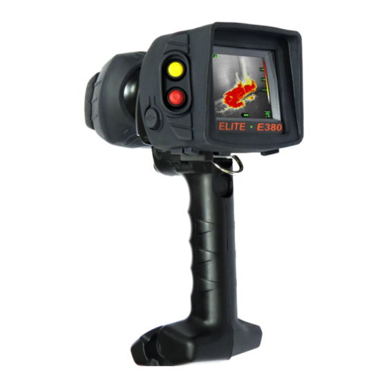
Summary of Contents for ISG INFRASYS E380
- Page 1 Operating Manual English © 2012, Infrared Systems Group Ltd. Rev. #1...
-
Page 2: Table Of Contents
Contents Introduction About Your Product More Information Regulatory Information Declaration of Conformity Safe Disposal Export Obligations End User Licence Standard Conditions Safety Warnings and Exclusions Getting Started Parts and Controls Charging the Battery Inserting and Removing the Battery General Operation Power On and Off On-screen Display Annotations and Meanings... -
Page 3: Introduction
More Information Should you have any queries with regard to this or any other ISG INFRASYS thermal imaging product, please contact our Customer Services team: Infrared Systems Group Ltd. -
Page 4: Regulatory Information
2.0 Regulatory Information Declaration of Conformity The EC Declaration of Conformity for your model of ISG INFRASYS thermal imager is supplied as a separate document on your Product Documents CD-ROM. Safe Disposal This symbol indicates the requirement for a separate waste collection for electronic equipment, batteries and accumulators. -
Page 5: Safety Warnings And Exclusions
Always perform a visual check on the equipment prior to use to validate that it has not been damaged or degraded. Never use the ISG INFRASYS thermal imager as the sole source of navigation. If system failure occurs, you may become disoriented or lost in a hostile environment, which could result in injury or death. - Page 6 The ISG INFRASYS thermal imager must be serviced only by authorised personnel. The thermal imager contains high voltage components and therefore, the user should never remove the cover due to risk of shock.
-
Page 7: Getting Started
Do not expose the battery charger unit and/or power adapter to rain or moisture. Do not attempt to use a charging device to charge a non-ISG INFRASYS approved battery. To install your Truck Charger, please refer to the installation guide enclosed. -
Page 8: Inserting And Removing The Battery
LED Indicators Power on Battery charging Battery charged Battery failure Inserting and Removing the Battery Inserting the Battery Insert the battery into the battery compartment. Push until the battery ‘clicks’ into place. Removing the Battery Press the release catch. Slide the battery out of the compartment. -
Page 9: General Operation
4.0 General Operation Power On and Off WARNING Always fit a fully charged battery prior to use in an emergency operation. Never disconnect the battery without undertaking the turn off procedure. Power On Press the Power button. LED lights continuously and start-up screen is displayed, signifying that the start-up sequence has been initiated. -
Page 10: Focus Range
Focus Range This product has an approximate focus range of 1.0 metre to infinity (∞). This means that objects that are imaged from less than 1.0 metre away may appear slightly blurred on the display. Over-Temperature Warning This indicator ( ) signifies that the thermal imager’s internal electronics have reached temperatures outside normal operating range, and therefore the thermal imager will shut down to preserve its life. -
Page 11: Colour Reference Bar
Colour Reference Bar The Colour Reference Bar provides a visual indication of the range of scene temperatures detected. It is displayed on the right-hand edge of the screen and provides a point of reference for the user to quickly identify the different temperature ranges in the scene. -
Page 12: Advanced Operation
5.0 Advanced Operation Zoom The Zoom feature enables the user to magnify the on-screen image to enhance imaging performance form a distance. Zoom On From Normal Imaging Mode, press the Red button. The live image is magnified by a factor of 2 and the X2 Zoom symbol is displayed. -
Page 13: Tac-Grip Operation
6.0 TAC-Grip Operation Attaching/Removing the Grip Attaching a Grip Align the grip with the mounting bracket on the underside of the thermal imager. Secure the grip using the locking wheel. Removing a Grip Undo the locking wheel and remove the grip. Parts &... -
Page 14: Video Capture
Video Capture (optional) Video Capture enables the user to record and save videos and still images, for review at a later date. To Switch On/Off Press the Red button, located on the handle. The LED lights orange. To Capture a Still Image Press the Yellow button. -
Page 15: Technical Specifications
7.0 Technical Specifications Engine Characteristics Detector Type: Uncooled Microbolometer Sensor Material: Amorphous Silicon Resolution: 384 x 288 Spectral Response: 8 µm to 14 µm Sensitivity (nominal): <50 mK Scene Update Rate: 50 Hz Dynamic Range: >1000°C (imaging extends below -40°C) Thermoelectric Cooler: None required Performance Characteristics Modes of Operation:... -
Page 16: Power Characteristics
Power Characteristics Battery Technology: Li-Ion Battery Weight: 0.2 kg Operating Time: >3.5 hours Recharge Time (nominal): <2.5 hours Recharge Cycles: 1000+ Operational Characteristics Pushbutton Controls: Power, Zoom, Hot Spot Tracker Start-up Time: < 10 seconds Video Standard: Image Optimisation: Automatic Colourisation: Dual-transparent colour Zoom:... -
Page 17: Additional Information
Warranty Disclaimer This warranty shall be null and void if ISG INFRASYS determines that the thermal imager or its accessories have been damaged by neglect, misuse, accident, abuse, power surges, over-exposure to heat, abnormal wear and tear, or other perils outside the design tolerances of the thermal imager. - Page 18 To maximise speed of return and repair, ISG INFRASYS operates the Service Direct facility, available to all customers within the European Union – please contact ISG INFRASYS for full details and to obtain an RMA code (see below). In all other cases, the end user shall return the unit to the authorised ISG INFRASYS distributor from whom the thermal imager was purchased.
-
Page 19: Trouble Shooting
9.0 Trouble Shooting If you are experiencing problems with your product, please refer to this checklist. If the problem persists, please contact ISG INFRASYS Customer Services or your local distributor. Power and Charging Issues Solutions Thermal imager will not turn on...


Need help?
Do you have a question about the E380 and is the answer not in the manual?
Questions and answers