Table of Contents
Advertisement
Advertisement
Table of Contents

Summary of Contents for Carvox CX999
-
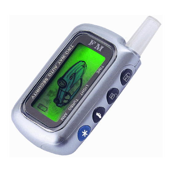
Page 2: Communication Unit Overview
Thank you for purchasing Long-Range Two-Way FM Vehicle Security System This vehicle security system features a state-of-the-art technology and FM design to give you maximum safety and satisfaction in using the system. 180 days 1) Please read this manual carefully before using this car alarm so that you'll take the full advantage of every marvelous features provided by the system. -
Page 3: System Wiring
TABLE OF BUTTONS CONFIGURATION QUICK REFERENCE GUIDE FOR SYSTEM WIRING Quick Reference Guide for System Wiring Ignition On or Triggered by Illegal Start Hood Opened Triggered by Microwave Sensor Keypad is Locked Silent Arming RTC Mode Mode Battery Life Indicator Auxiliary Output The System is in Arming Mode TURBO... -
Page 4: Features Description
FEATURES PROGRAMMING ROUNTINE FEATURES DESCRIPTION Standard Arming Mode Checklist of Options Parking Windows Rolling-up If you hear three more chirps after arming, maybe you need to re-check the doors to see whether they are properly closed. This chirp is called door zone bypass notification. This notification is given out when some door is not closed properly or if your car has a dome light delay. -
Page 5: Program Features
FEATURES PROGRAMMING ROUNTINE FEATURES DESCRIPTION Program Features STEP1 STEP2 STEP3 d: You may select an optional field disturbance sensor such as microwave sensor or radar sensor, your system can react to any intrusions into this field with the full triggered sequence. Silent Arming Mode Four STEP4... -
Page 6: System Installation
SYSTEM INSTALLATION FEATURES DESCRIPTION 1.Press Button once: The siren chirps once. The system is armed. All zones are active. LED indicator blinks once and then pauses for 2.0 seconds and then repeats. 2.Press Button a second time within 5 seconds: The siren chirps once again. The shock sensor zone is now bypassed. -
Page 7: Query Function
SYSTEM INSTALLATION FEATURES DESCRIPTION Query Function Panic Mode The system will enter Parking Panic Mode To stop Panic Mode at any time, press button for 2.0sec again or press button for 0.5sec. You may select whether disarm and unlock doors when trunk released by options.(This function is suitable for cars with electric trunk opener) Auxiliary Output (Programmable) Turn on... - Page 8 FEATURES DESCRIPTION SYSTEM INSTALLATION Remote Engine Start (Must Need Remote Start Module) Pin 4: GREY WIRE: Hood Pin Input (-). Connect this wire to the hood pin switch. The switch must supply a ground output(-)when switch is opened. This input will disable or shut down the remote start when the hood is opened.
- Page 9 SYSTEM INSTALLATION FEATURES DESCRIPTION Pin4: Blue/Black: Unlock #30 Common (Output) Turbo/Short Run Pin5: Brown/Black: Unlock #87 Normally Open (Input) Pin6: Violet/Black: Lock #87a Normally Closed Pin7: Green/Black: Lock #30 Common (Output) Pin8: White/Black: Lock #87 Normally Open (Input) Park the vehicle and set parking brake. Remove your foot from the brake pedal Pin9: Red: Constant +12V Input.
-
Page 10: Valet Mode
FEATURES DESCRIPTION SYSTEM INSTALLATION Valet Mode Harness Description 5 Heavy Gauge Starter Harness in the Starter Module (Ignition Switch Interface) Purple Wire: Starter Output (+). Connect to the vehicle's starter wire. hold ORANGE WIRE: Accessory Output (+). Connect to the accessory wire coming from the ignition switch switch 3 seconds that supplies power to the heater/air-conditioner. - Page 11 SYSTEM INSTALLATION FEATURES DESCRIPTION System Installation 1.Due to the complexity of this system, installation must only be performed by an authorized dealer. 2.Thoroughly read and become familiar with the installation instructions before beginning the installation. 3.Review system contents: a.Main Control Unit b.Siren c.Communication unit with built-in Shock Sensor and Valet Switch d.Starter Kill Relay...
- Page 12 FEATURES DESCRIPTION FEATURES DESCRIPTION The shock sensor is built in the communication unit. You can adjust the shocking sensitivity by changing the position "H" , "M" , or " L" of the adjustment switch on the communication unit. Door Status Warning (Programmable) switch The lights will flash to inform you that some door is not closed well.
Need help?
Do you have a question about the CX999 and is the answer not in the manual?
Questions and answers