Advertisement
Table of Contents
- 1 Important Information
- 2 Hazard Definitions
- 3 Table of Contents
- 4 Pre-Installation
- 5 Boiler Assembly
- 6 Gas Control System Assembly
- 7 Water Trim and Piping
- 8 Gas Piping
- 9 Venting
- 10 Electrical
- 11 System Start-Up
- 12 Service
- 13 Repair Parts
- Download this manual
See also:
Operation & Installation Manual
INSTALLATION, OPERATING AND
SERVICE INSTRUCTIONS FOR
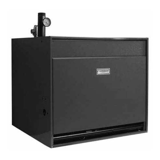
SERIES 8H / 8HE
GAS - FIRED BOILER
3050579
This manual must only be used by a qualified heating installer/service technician.
BEFORE installing, read all instructions in this manual and all other information
shipped with the boiler. Post all instructions and manuals near the boiler for
reference by service personnel. Perform steps in the order given. Failure to comply
could result in severe personal injury, death or substantial property damage.
Commercial Boilers
www.burnhamcommercial.com
Price - $5.00
81416023R5 - 4/15
1
Advertisement
Table of Contents


Need help?
Do you have a question about the 805H and is the answer not in the manual?
Questions and answers