Table of Contents
Advertisement
INSTALLATION INSTRUCTION, PARTS LIST
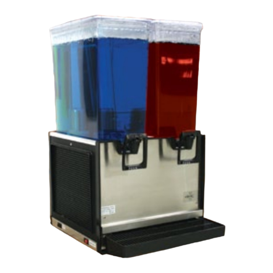
BEVERAGE DISPENSER (STARLINE)
The information contained in this document is subject to change without notice.
SCHROEDER AMERICA MAKES NO WARRANTY OF ANY KIND WITH REGARD TO THIS MATERIAL, INCLUDING,
BUT NOT LIMITED TO, THE IMPLIED WARRANTIES OF MERCHANTABILITY AND FITNESS FOR A PARTICULAR
PURPOSE. SCHROEDER AMERICA shall not be liable for errors contained herein or for incidental consequential
damages in connection with the finishings, performance, or use of this material.
This document contains proprietary information which is protected by copyright. All right reserved.
This manual must be read and understood before the installation and operation of this dispenser.
AND CONFIGURATION GUIDE
FOR THE
NON-CARBONATED
Dispenser Model No. 900
NOTICE:
© Copyright 2008 by Schroeder America, all rights reserved.
THIS DOCUMENT CONTAINS IMPORTANT INFORMATION
Schroeder America
5620 Business Park • San Antonio, TX 78218
210.662.8200 • Fax: 210.667.2600 • www.schroederamerica.com
Toll-Free 877.404.2488
Please refer to the Schroeder America website (www.schroederamerica.com)
for information relating to Schroeder America installation and Service
Manuals, Instruction Sheets, Technical Bulletins, Service Bulletins, etc.
Rev: 03/12
PN: 805-0001
Advertisement
Table of Contents

Related Manuals for Schroeder America S-1


Summary of Contents for Schroeder America S-1
- Page 1 BUT NOT LIMITED TO, THE IMPLIED WARRANTIES OF MERCHANTABILITY AND FITNESS FOR A PARTICULAR PURPOSE. SCHROEDER AMERICA shall not be liable for errors contained herein or for incidental consequential damages in connection with the finishings, performance, or use of this material.
-
Page 2: Overall Dimensions
Request a written inspection report from Claims Inspector to substantiate any necessary claim. File claim with the delivering carrier, not with Schroeder America. After unit has been unpacked, remove shipping tape and other material. - Page 3 A minimum of 12 inches air space must be maintained between unit sides and back panels and nearest wall or obstruction to allow for circulating air to cool refrigeration system. C. Adequate clearance must be maintained above unit to replenish product supply and also remove bowl cover, bowl, and spray tube for periodic cleaning.
-
Page 4: Preparation For Operation
NOTE Do not move unit after positioning or seal from base to countertop will be broken. Lower unit into operating position on countertop to complete seal from base to countertop. Apply additional sealant around bottom of base. Seal must have a minimum radius of 1/2”... -
Page 5: Periodic Inspection
Make sure spray tube assemblies are operating properly and circulating product in bowl. C. Make sure drip tray is clean and clean cup rest is in place in drip tray. WARNING Disconnect electrical power to unit to prevent personal injury before attempting any internal maintenance. -
Page 6: Cleaning Brush
Check clearance between bottom side of platform and spray drive magnet for clearance specified in preceding IMPORTANT note. If clearance is not adequate, loosen set screw and slide spray drive magnet up or down to proper clearance, then securely tighten the set screw. (Page 14) Install front panel and secure with the two screws removed in step 1. - Page 7 Grasp dispensing valve bonnet. Turn bonnet to the left (counterclockwise), then lift bonnet up and out of valve. Using CLEANING BRUSH (Item 1), thoroughly clean inside of dispensing valve body with warm water. Using CLEANING BRUSH, thoroughly clean dispensing valve bonnet with warm water.
-
Page 8: Troubleshooting
IMPORTANT Excessive accumulation of dust, lint, and grease on condenser coil or filter will restrict air flow through condenser coil and cause loss of cooling efficiency. Perform following procedure to clean condenser coil. Unplug power cord from electrical outlet. Remove screws securing back panel, then remove panel for access to filter and condenser coil. - Page 9 2. Product leaking Bowl gasket improperly installed. A. Reinstall bowl gasket. RIBBED SIDE OF BOWL GASKET SHOULD ALWAYS FACE EVAPORATOR DOME BASE. B. Worn or damaged bowl gasket. Replace bowl gasket. 3. Compressor does A. Refrigeration switch in the “OFF” Turn switch to not operate position.
- Page 10 5. Condenser fan motor does NOTE: If overload protector cuts out compressor, condenser not operate fan motor will continue to operate; otherwise, troubleshooting condenser fan motor is the same as for “COMPRESSOR DOES NOT OPERATE”. A. Jumper wires loose or Tighten connection disconnected.
- Page 11 WIRING DIAGRAM - STARLINE...
- Page 12 LOOSE SHIPPED PARTS BRUSH, SPRAYERS, STARLINE SPRAY TUBE & IMPELLER ASSY-5 GAL P.N. 316-0002 P.N. 631-0006 CUP REST - S1 CUP REST - S2 BOWL ASSY W/DECALS P.N. 265-0016 P.N. 265-0057 P.N. 631-0008 DRIP TRAY - S2 DRIP TRAY - S1 BOWL COVER P.N.
-
Page 13: Installation Diagrams
INSTALLATION DIAGRAMS BOWL GASKET BOWL GASKET EVAPORATOR FIG. 4.1 FIG. 4.2 INSTALLING BOWL GASKET INSTALLING BOWL FIG. 4.3 INSTALLING SPRAY TUBE ASSEMBLY... - Page 14 MAGNETIC IMPELLER DRIVE MOTOR ASSEMBLY * IMPORTANT Clearance between bottom side of cabinet cover and magnetic impeller drive must be 1/16-inch which is the approximate size of the allen wrench used to loosen the hex-type setscrews.
- Page 15 FAUCET PARTS AND ASSEMBLIES P.N. 631-0065 BONNET P.N. 265-0058 SPRING P.N. 215-0004 P.N. 631-0007 SHAFT P.N. 279-0019 SEAT CUP P.N. 210-0024 FAUCET BODY - 3” P.N. 265-0059 FAUCET ASSY 3” FAUCET ASSY, W/PULL HANDLE P.N. 645-0005 P.N. 645-0119 3” FAUCET ASSY W/FAUCET 3”...
- Page 16 STARLINE SINGLE BOWL ASSEMBLY (ILL. ONLY)
- Page 17 STARLINE SINGLE BOWL ASSEMBLY PART NUMBERS NEW PART# OLD PART# DESCRIPTION 265-0016 04-2250-039 Cup Rest 265-0064 04-2240-039 Drip Tray 319-0008 96-0681-000 Drip Tray Panel 319-0183 04-0188-000 Front Panel 265-0337 04-1250-000 Grill, Side 319-0178 96-0717-001 Panel, Rear 300-0001 96-0980-000 Compressor, Danfoss 503-0003 04-0212-000 Fan Motor...
- Page 19 STARLINE DUAL BOWL ASSEMBLY PART NUMBERS NEW PART# OLD PART# DESCRIPTION 265-0057 04-1360-039 Cup Rest 265-0222 04-1340-039 Drip Tray 319-0011 96-0887-000 Drip Tray Panel 319-0174 96-0886-000 Front Panel 265-0337 04-1250-000 Grill, Side 319-0171 96-0710-001 Panel, Rear 300-0002 96-0985-000 Compressor, Danfoss 304-0005 96-1015-000 Fan Motor...
- Page 20 The Period of Warranty is (i) one (1) year from the date of installation, or (ii) fifteen (15) months from the date of shipment by Schroeder America of a product covered hereby, whichever time period elapses first. For products incorporating a sealed refrigeration system the Period of Warranty, with respect to the sealed refrigeration system only (defined as the compressor, evaporator, condenser, and interconnection tubing [not to include access valves]), is three (3) years from the date of installation or forty (40) months from the date of shipment by Schroeder America, whichever time period elapses first.
Need help?
Do you have a question about the S-1 and is the answer not in the manual?
Questions and answers