Table of Contents
Advertisement
AIR CONDITIONERS CITY MULTI
TECHNICAL & SERVICE MANUAL
Series PDFY
<Indoor unit>
PDFY-10NMU-A,PDFY-16NMU-A
Models
PDFY-24NMU-A,PDFY-32NMU-A
PDFY-40NMU-A,PDFY-48NMU-A
Ceiling Concealed Built-in
2002
CONTENTS
SAFETY PRECAUTIONS ·························1
1. FEATURES············································2
2. PART NAMES AND FUNCTIONS ········3
3. SPECIFICATION ···································5
4. OUTLINES AND DIMENSIONS············7
5. WIRING DIAGRAM ·······························
7. TROUBLE SHOOTING························12
8. DISASSEMBLY PROCEDURE ···········17
For use with the R22
9
Advertisement
Table of Contents

Related Manuals for Mitsubishi Electric PDFY-10NMU-A


Summary of Contents for Mitsubishi Electric PDFY-10NMU-A
-
Page 1: Table Of Contents
2002 AIR CONDITIONERS CITY MULTI TECHNICAL & SERVICE MANUAL Ceiling Concealed Built-in Series PDFY <Indoor unit> PDFY-10NMU-A,PDFY-16NMU-A Models PDFY-24NMU-A,PDFY-32NMU-A PDFY-40NMU-A,PDFY-48NMU-A CONTENTS SAFETY PRECAUTIONS ·························1 1. FEATURES············································2 2. PART NAMES AND FUNCTIONS ········3 3. SPECIFICATION ···································5 4. OUTLINES AND DIMENSIONS············7 5. WIRING DIAGRAM ·······························... -
Page 3: Safety Precautions
Install the air unit at a place that can withstand its weight. is shorted and operated forcibly, or parts other than those specified - Inadequate strength may cause the unit to fall down, resulting in by Mitsubishi Electric are used, fire or explosion may result. injuries. •... -
Page 4: Features
FEATURES Ceiling Concealed Built-in Series PDFY Indoor unit Cooling capacity/Heating capacity Models Btu / h PDFY-10NMU-A 2.8 / 3.2 9500 / 10800 PDFY-16NMU-A 4.6 / 5.5 15700 / 18700 PDFY-24NMU-A 6.9 / 7.4 23600 / 25400 PDFY-32NMU-A 9.1 / 10... -
Page 5: Part Names And Functions
PART NAMES AND FUNCTIONS Indoor (Main) Unit Air outlet Air inlet Remote controller [PAR-20MAA] Once the controls are set, the same operation mode can be repeated by simply pressing the ON/OFF button. Operation buttons 4 5 6 8 7 9 1 [Room temperature adjustment] Button 7 [Up/down airflow direction] Button 2 [Timer/continuous] Button... - Page 6 Display I KLJ (A) Current time/Timer (B) Centralized control (C) Timer ON (D) Abnormality occurs (E) Operation mode: COOL, DRY, AUTO, FAN, HEAT (F) Preparing for Heating mode (G) Defrost mode (H) Set temperature Power ON (J) Louver (K) Not available function (L) Ventilation (M) Function setting mode (N) Test run mode...
-
Page 7: Specification
SPECIFICATION 3-1. Specification PDFY-10NMU-A PDFY-16NMU-A PDFY-24NMU-A Voltage ~ 208-230V Power sourse 60Hz Frequency Capacity Cooling 9500 15700 23600 Heating 10800 18700 25400 Power input Cooling 0.12 0.15 0.17 0.12 0.15 0.17 Heating Current Cooling 0.61-0.68 0.77-0.85 0.87-0.96 (208-230V) Heating 0.61-0.68 0.77-0.85... - Page 8 3-2. Electrical parts specifications Model PDFY- PDFY- PDFY- PDFY- PDFY- PDFY- Symbol Parts 10NMU-A 16NMU-A 24NMU-A 32NMU-A 40NMU-A 48NMU-A name Tranrsformer (Primary) 240V 60Hz (Secondary) (23.5V 0.9A) Room temperature TH21 Resistance 0˚C/15kΩ,10˚C/9.6kΩ,20˚C/6.3kΩ,25˚C/5.4kΩ,30˚C/4.3kΩ,40˚C/3.0kΩ thermistor Liquid pipe TH22 Resistance 0˚C/15kΩ,10˚C/9.6kΩ,20˚C/6.3kΩ,25˚C/5.4kΩ,30˚C/4.3kΩ,40˚C/3.0kΩ thermistor Gas pipe TH23 Resistance 0˚C/15kΩ,10˚C/9.6kΩ,20˚C/6.3kΩ,25˚C/5.4kΩ,30˚C/4.3kΩ,40˚C/3.0kΩ...
-
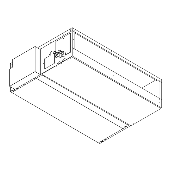
Page 9: Outlines And Dimensions
OUTLINES AND DIMENSIONS PDFY-10,16,24,32NMU-A... - Page 10 PDFY-40,48NMU-A...
-
Page 11: Wiring Diagram
WIRING DIAGRAM PDFY-10,16,24,32NMU-A... - Page 12 PDFY-40,48NMU-A...
-
Page 13: Refrigerant System Diagram
REFRIGERANT SYSTEM DIAGRAM Gas pipe thermistor TH23 Gas pipe Liquid pipe thermistor TH22 Flare connection Heat exchanger Linear expansion valve Strainer (#100mesh) Strainer (#100mesh) Room temparature thermistor TH21 Capacity PDFY-10,16NMU-A PDFY-24,32NMU-A PDFY-40,48NMU-A Item Gas pipe ø12.7<1/2F> ø15.88<5/8F> ø19.05<3/4F> Liquid pipe ø6.35<1/4F>... -
Page 14: Trouble Shooting
TROUBLE SHOOTING 7-1. How to check the parts Parts name Check points Room temparature Disconnect the connector, then measure the resistance using a tester. thermistor (TH21) (Sorrounding temperature 10˚C~30˚C) Liquid pipe thermistor (TH22) Normal Abnormal Gas pipe thermistor (Refer to the thermistor) (TH23) 4.3kΩ... - Page 15 <Thermistor Characteristic graph> < Thermistor for lower temperature > Room temparature thermistor(TH21) Thermistor for Liquid pipe thermistor(TH22) lower temperature Gas pipe temparature thermistor(TH23) Drain sensor(DS) =15kΩ ± 3% Thermistor R Fixed number of B=3480kΩ ± 2% Rt=15exp { 3480( 273+t 0˚C 15kΩ...
- Page 16 <Output pulse signal and the valve operation> Output Output (Phase) Closing a valve Opening a valve : 4 ø1 The output pulse shifts in above order. ø2 1. When linear expansion valve operation stops, all output phase become OFF. ø3 2.
- Page 17 Operation by switch Switch Pole Remarks Function Thermistor<Intake temperature Indoor unit Built-in remote controller Address board detection>position Filter crogging detection Provided Not provided <At delivery> Filter life 2,500hr 100hr 1 2 3 4 5 6 7 8 9 10 Air intake Effective Not effective Remote indication switching...
- Page 18 Switch Pole Operation by switch Remarks Address board 208V 230V 208V 230V 208V 230V 208V 230V <At delivery> 80Pa 100Pa 50Pa 60Pa 50Pa 60Pa 50Pa 60Pa 80Pa 100Pa 80Pa 100Pa 50Pa,100Pa 60Pa,115Pa Option 30Pa 40Pa 30Pa 40Pa 30Pa 40Pa 30Pa 40Pa For other models, change the setting of static pressure by replacing the connector.
-
Page 19: Disassembly Procedure
DISASSEMBLY PROCEDURE 8-1 CONTROL BOX Be careful removing heavy parts. OPERATING PROCEDURE PHOTOS 1.Removing the control box cover (1)Remove the fixing screws(two) of the cover(A) and remove the cover. Fig.1 8-2 THERMISTOR (Liquid piping temperature detection) OPERATING PROCEDURE PHOTOS 1.Removing the cover (1)Remove the fixing screws(two) of the cover(C) and remove the cover. - Page 20 8-3 THERMISTOR (Intake air temperature detection) Be careful removing heavy parts. OPERATING PROCEDURE PHOTOS 1.Removing the thermistor and thermistor holder (1)Pull out the thermistor holder(F) and thermistor (G) which are fixed the control box. Fig.1 (F),(G) 8-4 DRAINPAN OPERATING PROCEDURE PHOTOS 1.Removing the cover (1)Remove the fixing screws of the cover(H) and...
- Page 21 8-5 THERMISTOR (Gus piping temperature detection) OPERATING PROCEDURE PHOTOS 1.Removing the cover (1)Remove the fixing screw of the cover(J) and remove the cover. 2.Removing the thermistor (1)Remove the thermistor(K), from the thermistor holder(L), which are installed on the copper tube. Fig.1 Fig.2 (K),(L)
-
Page 22: Fan And Fan Motor
8-6 FAN and FAN MOTOR OPERATING PROCEDURE PHOTOS 1.Removing the filter (1)Press the tabs of the filter and remove the filter in the direction of the arrow 1. 2.Removing the bottom plate (1)Remove the fixing screws (two) of the bottom plate(N) and remove the plate. -
Page 23: Heat Exchanger
8-7 HEAT EXCHANGER OPERATING PROCEDURE PHOTOS 1.Removing the drainpan with procedure 8-4 2.Removing the cover(J) with procedure 8-5 3.Removing the Heat exchanger (1)Remove the fixing screws of the heat exchang- er(S) and remove the heat exchanger. Fig.1 Fig.2... - Page 24 New publication, effective Sep. 2002 Issued in Sep. 2002 MEE02K124 Specifications subject to change without notice...
- Page 25 3400 Lawrenceville Suwanee Road Suwanee, Georgia 30024 ● Toll Free: 800-433-4822 Toll Free Fax: 800-889-9904 ● www.mrslim.com Specifications are subject to change without notice.
Need help?
Do you have a question about the PDFY-10NMU-A and is the answer not in the manual?
Questions and answers