
Subscribe to Our Youtube Channel
Related Manuals for Unitor UWI 320 TP


Summary of Contents for Unitor UWI 320 TP
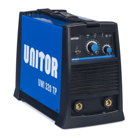
- Page 1 Instruction manual Unitor Welding Inverter UWI 320 TP MMA (Stick) and TIG welder Revision date: 23/09/2014 Page 1 of 24...
-
Page 2: Table Of Contents
CONTENTS 1. GENERAL DESCRIPTION 2. TECHNICAL DATA 3. INSTALLATION 4. FRONT AND BACK PANEL 5. WELDING 6. ROUTINE MAINTENANCE 7. TROUBLESHOOTING 8. WIRING DIAGRAM 9. COMPONENTS AND SPARES 10. ACCESSORIES 11. SAFETY INSTRUCTIONS DO NOT INSTALL, OPERATE OR REPAIR THIS EQUIPMENT WITHOUT READING THIS MANUAL INCLUDING THE SAFETY INSTRUCTIONS Revision date: 23/09/2014 Page 2 of 24... -
Page 3: General Description
Total Protection function with indicator light prevents machine damage if one phase in the primary power supply falls out. IDENTIFY COMPONENTS Unitor Welding Inverter UWI 320TP, product number 191- 320320 is delivered with Carrying strap mounted on the machine 1 pce... -
Page 4: Technical Data
2 TECHNICAL DATA Type of welding machine Three-phase static transformer rectifier frequency converter, DC output. Processes MMA (Stick electrode / SMAW) TIG (GTAW) Safety Marking Suitable for use in areas with increased electric shock hazard X: Duty cycle Duty Cycle is percentage of 10 minutes that unit can weld at rated load without overheating. It refers to a 40°C environmental temperature. - Page 5 = Welding current. Range 10 – 320A = No-load voltage Is the voltage between welding terminals (touchable voltage) when the machine is idle and equipped with a voltage reduction function for operator safety. Low value means high operator safety, and with this in mind this machine satisfies the world’s strictest regulation: AS 1674.2-2007 Safety in welding and allied processes (Australian standard) which allows for maximum 35V.
-
Page 6: Installation
Select a suitable location The UWI 320 TP inverter welder has an IP23S rating. Locate the welder in a dry location where there is free circulation of clean air into the louvers in the back and out the front of the unit. -
Page 7: Front And Back Panel
4 FRONT AND BACK PANEL Description 1. Active VRD signal. When lit this shows that the Voltage Reducing Device is active, reducing the voltage across the welding sockets. This will happen within 2 seconds after the welding arc is broken to protect the welder from electric chock. Full arc striking voltage will automatically be re-established when the welding circuit is re- established by touching the electrode to the work-piece 2. -
Page 8: Welding
5 WELDING MMA (SMAW stick electrode) welding 1 Electrode Select MMA welding (selector switch up). 2 Workpiece Connect ground (return) cable with good contact to 3 Arc the work piece. Select polarity and amperage as recommended for the electrode and start arc as follows: Drag electrode across work piece like striking a Match and lift electrode slightly after touching work. - Page 9 6 PARALLEL CONNECTION Two pcs UWI-320TP may be parallel connected and will then supply up to 640A current for stick electrode welding and, more important, for Air Carbon Arc gouging. This is done as follows: Set both machines to MMA welding (selector switch up). Set both machines to remote control and if extensions are necessary use same length remote control cables from each machine to the work site where the remote control parallel connection kit, product number...
-
Page 10: Routine Maintenance
7 ROUTINE MAINTENANCE Checkpoint Action Interval Primary plug Check connections 3 months or more and socket and stretch relief often if needed Check for damage and replace if 3 months or more Primary cable necessary often if needed Primary cable Check for damage 3 months or more stretch relief... -
Page 11: Troubleshooting
8 TROUBLESHOOTING SYMPTOM POSSIBLE SOLUTION REASON Mains fuses blown Machine is not plugged in Broken primary cable Primary power No output, no warning does not reach the Cable connection to machine is loose light, fan not running machine Machine not switched on On/off switch damaged Voltage protection Too high or too low input voltage, should be... -
Page 12: Wiring Diagram
9 WIRING DIAGRAM Revision date: 23/09/2014 Page 12 of 24... -
Page 13: Components And Spares
10 COMPONENTS AND SPARES Revision date: 23/09/2014 Page 13 of 24... - Page 14 040.0004.0004 Selector Spare part kit for UWI-320TP includes power board, necessary additional components and complete instructions for replacement Order no191-320323 For ordering spares please state: Model: UWI 320 TP Serial no: …………. Pos no: …………. Code: .…………. Revision date: 23/09/2014...
-
Page 15: Accessories
11 ACCESSORIES Basic accessories for UWI-320 Basic accessories kit for UWI-320 196 670406 Consisting of: (Order numbers to be used when re-ordering) Flip-Vision shield with flip-up frame, head band and filter shade 11 glass 196 709485 Long lined welding gloves, 1pair 196 632786 (re-ordering number is for 6 pairs) Electrode holder with 3m cable and connector... - Page 16 TIG torch T-200 Order number 197-200000 Pos. Order number Unit Product description 197-551192 Short back-cap 197-551200 Long back-cap 197-613767 Heat shield 197-551168 Collet 1.6mm 197-551150 Collet 2.4mm 197-551184 Collet body 1.6 mm 197-551176 CoIlet body 2.4 mm 197-551135 Alumina nozzle 6 197-551127 Alumina nozzle 7 197-674710...
-
Page 17: Safety Instructions
12 SAFETY INSTRUCTIONS Arc Welding Hazards The safety information given below is only a summary of the more complete safety information found in the Safety Standards listed in Section 1-5. Read and follow all Safety Standards. Only qualified persons should install, operate, maintain, and repair this unit. During operation, keep everybody, especially children, away. - Page 18 FUMES AND GASES can be hazardous. Welding produces fumes and gases. Breathing these fumes and gases can be hazardous to your health. Keep your head out of the fumes. Do not breathe the fumes. If inside, ventilate the area and/or use exhaust at the arc to remove welding fumes and gases. If ventilation is poor, use an approved air-supplied respirator.
- Page 19 HOT PARTS can cause severe burns. Do not touch hot parts bare handed. Allow cooling period before working on gun or torch. MAGNETIC FIELDS can affect pacemakers. Pacemaker wearers keep away. Wearers should consult their doctor before going near arc welding, gouging, or spot welding operations.
- Page 20 MOVING PARTS can cause injury. Keep away from moving parts such as fans. Keep all doors, panels, covers, and guards closed and securely in place. H.F. RADIATION can cause interference. High-frequency (H.F.) can interfere with radio navigation, safety services, computers, and communications equipment.
- Page 21 ₪ ₪ ₪ ₪ ₪ ₪ ₪ ₪ ₪ ₪ ₪ ₪ UNITOR WELDING INVERTER We hereby state that the machine type UWI 320 TP ₪ ₪ ₪ ₪ ₪ ₪ ₪ ₪ ₪ ₪ ₪ ₪ ₪ ₪ ₪...
- Page 22 NOTES ………………………………………………………………………………………………… ………………………………………………………………………………………………… ………………………………………………………………………………………………… ………………………………………………………………………………………………… ………………………………………………………………………………………………… ………………………………………………………………………………………………… ………………………………………………………………………………………………… ………………………………………………………………………………………………… ………………………………………………………………………………………………… ………………………………………………………………………………………………… ………………………………………………………………………………………………… ………………………………………………………………………………………………… ………………………………………………………………………………………………… ………………………………………………………………………………………………… ………………………………………………………………………………………………… ………………………………………………………………………………………………… ………………………………………………………………………………………………… ………………………………………………………………………………………………… ………………………………………………………………………………………………… FOR FULL INFORMATION ON THE UNITOR WELDING OFFER Revision date: 23/09/2014 Page 22 of 24...
- Page 23 USE THE UNITOR WELDING HANDBOOK FOR MARITIME WELDERS You can download it here http://www.wilhelmsen.com/services/maritime/companies/buss/DocLit/PorductLiterature/Pages/Maintenanceandrepair.aspx …or contact Wilhelmsen Ships Service for a paper copy Revision date: 23/09/2014 Page 23 of 24...
- Page 24 Fraser/surrey Gaspe Gros Caouna Halifax Hamilton Harbour Grace Holyrood Kitimat Long Pond Marytown Montreal Nanaimo New Instruction manual Westminster Bc Pictou/halifax Pointe Aux Pic.quebec Port Alfred Port Cartier Port Colborne Port Hawkesbury Port Mellon Port Moody Port Of Quebec Port Weller Powell River Prince Rupert Roberts Bank Saint John Sarnia, Ontario Sept Iles Seven Islands Sorel Souris/ halifax Squamish St.
Need help?
Do you have a question about the UWI 320 TP and is the answer not in the manual?
Questions and answers