
Related Manuals for EnGenius ENH710EXT


Summary of Contents for EnGenius ENH710EXT
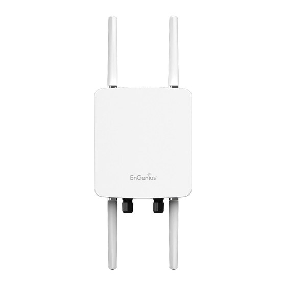
- Page 1 Business Solutions User Manual ENH710EXT version 1.0 Dual Band Long Range Wireless N600 Outdoor Access Point...
- Page 2 IMPORTANT To install this Access Point please refer to the Quick Installation Guide included in the product packaging.
-
Page 3: Table Of Contents
Chapter 8 Management ..........48 Computer Settings............12 Hardware Installation..........15 Management VLAN Settings........49 Mounting the ENH710EXT........16 Advanced Settings............. 50 CLI Settings/Email Alert..........51 Chapter 3 Configuring Your Access Point....20 Time Zone. -
Page 4: Chapter 1 Product Overview
Chapter 1 Product Overview... -
Page 5: Key Features/Introduction
Features and specifications subject to change without notice. Trademarks and registered trademarks are the property of their respective owners. For United States of America: Copyright © 2014 EnGenius Technologies, Inc. All... - Page 6 rights reserved.
-
Page 7: System Requirements
The following are the Minimum System Requirements in The ENH710EXT is easy to install in virtually any location order to configure the device. with its included PoE (Power over Ethernet) injector for quick outdoor installation. -
Page 8: Package Contents
Package Contents The ENH710EXT package contains the following items:* • ENH710EXT Access Point • 2 detachable 5 dBi 2.4 GHz Omni-directional Antenna • 2 detachable 7 dBi 5 GHz Omni-directional Antenna • Power Adapter • PoE Injector (EPE-48GR) • Grounding Cable •... -
Page 9: Technical Specifications
Technical Specifications WDS Detail Standard: IEEE802.11a/n on 5 GHz WDS AP IEEE802.11b/g/n on 2.4 GHz WDS Bridge IEEE802.3at WDS Station Antenna Optimal Performance 4 External N-type Antennas Distance Control (Ack Timeout) 2 x detachable 5dBi 2.4GHz Omni-directional Antennas Multicast Supported 2 x detachable 7dBi 5GHz Omni-directional Antennas Band Steering Physical Interface... - Page 10 Reinforcement Security WEP Encryption-64/128/152 bit WPA/WPA2 Enterprise (WPA-EAP using TKIP or AES) Hide SSID in beacons MAC address filtering up to 32 MACs per SSID Https Support QoS (Quality of Service) Complaint with IEEE 802.11e standard Physical/Environment Conditions Operating: Temperature: -4 °F to 158 °F (-20 °C to 70 °C) Humidity (non-condensing): 90% or less Storage: Temperature: -22 °F to 176 °F (-30 °C to 80 °C)
-
Page 11: Physical Interface
Physical Interface Dimensions and Weights Length: 280.48mm (11.22”) Width: 217.65mm (8.58”) Depth: 55.50mm (2.1”) Weight: 1.88Kg (4.17 lbs) 1 2.4 GHz Antennas: Detachable 5 dBi 2.4 GHz Omni-directional 2 5 GHz Antennas: Detachable 7 dBi 5 GHz Omni-directional 3 LAN Port 1 (802.3at PoE Input): Ethernet port for RJ-45 cable. 4 LAN Port 2: Ethernet port for RJ-45 cable. -
Page 12: Chapter 2 Before You Begin
Chapter 2 Before You Begin... -
Page 13: Computer Settings
Computer Settings Windows XP/Windows 7/Windows 8 In order to use the ENH710EXT, you must first configure the TCP/IPv4 connection of your Windows OS computer system. 1a. Click the Start button and open the Control Panel Windows XP Windows 7... - Page 14 2a.In Windows XP, click Network Connections. 1b. Move your mouse to the lower right hot corner to display the Charms Bar and select the Control Panel in Windows 8 OS. 2b.In Windows 7/Windows 8, click View Network Status and Tasks in the Network and Internet section, then select Change adapter settings.
- Page 15 OK. Note: Ensure that the IP address and Subnet mask are on the same subnet as the device. For example: ENH710EXT IP address: 192.168.1.1 PCIPaddress:192.168.1.2–192.168.1.255 PC Subnet mask: 255.255.255.0 4. Select Internet Protocol Version 4 (TCP/IPv4) and then...
- Page 16 4. In Configure IPv4, select Manually. Applications folder or selecting it in the Apple Menu). 5. Enter an IP address that is different from the ENH710EXT 2. Select Network in the Internet & Network section. and Subnet mask then press OK.
-
Page 17: Hardware Installation
Ensure that the 2.4 GHz/5 GHz WLAN light is on (it will be green for both 5 GHz and 2.4 GHz). Powe c) Ensure that the LAN (Computer/ENH710EXT Outle Connection) light is on (it will be green). Note: The Access Point supports both IEEE 802.3at PoE d) Once all three lights are on, proceed to set up the (Power over Ethernet) or the included power injector. -
Page 18: Mounting The Enh710Ext
Mounting the ENH710EXT Using the provided hardware, the ENH710EXT can be attached to a wall or a pole. 1. Wall Mount Kit: 260x180x7 (mm) 2. Pole Mount Kit 140x112x33 (mm) (10.2" x 7.09" x 0.28") (5.51" x 4.41" x 1.30") 3. - Page 19 To attach the ENH710EXT to a wall using wall mounting kit. 1. Mark the four locations of the mounting holes on the 3. Place the lock and flat washers on the four hex cap screws flat mounting surface. and drive the screws to attach the bracket to the back of the Access Point.
- Page 20 To attach the ENH710EXT to a pole using the provided pole mounting kit: 1. Place the lock and flat washers on the four hex cap screws tabs on the Pole Mount Bracket . and drive the screws to attach the bracket to the back of 4.
- Page 21 To install the ground cable on the ENH710EXT 1. Use the attached screws to pass the ground cable as 2. Assemble the ground cable on the device. shown in the figure below. Length: 1.8m (5.9”)
-
Page 22: Chapter 3 Configuring Your Access Point
Chapter 3 Configuring Your Access Point... -
Page 23: Default Settings./Web Configuration
3. If successful, you will be logged in and see the Chrome) and enter the IP Address http://192.168.1.1 ENH710EXT User Interface. Note: If you have changed the default LAN IP Address of the Access Point, ensure you enter the correct IP Address. -
Page 24: Chapter 4 Building A Wireless Network
Chapter 4 Building a Wireless Network... -
Page 25: Access Point Mode
The stations and clients must be configured to use the same SSID (Service Set Identifier) and security password to associate with the ENH710EXT. The ENH710EXT supports up to eight (8) SSIDs per band at the same time for secure access. -
Page 26: Client Bridge Mode
If you use the client bridge mode in the ENH710EXT, you can use the AP Detection feature to scan for Access Points within range. When you find an Access Point, configure the ENH710EXT to use the same SSID and Security Password as... -
Page 27: Wds Ap Mode
WDS AP Mode The ENH710EXT also supports WDS AP mode. This operating mode allows wireless connections to the ENH710EXT using WDS technology. In this mode, configure the MAC addresses in both Access Points to enlarge the wireless area by enabling... -
Page 28: Wds Bridge Mode
ENH710EXT device. Use this mode when two wired LANs located a small distance apart want to communicate with each other. The best solution is to use the ENH710EXT to wirelessly connect two wired LANs, as shown in the following diagram. -
Page 29: Wds Station Mode
WDS Station Mode Station mode expands the WDS by receiving a wireless signal/service and sharing it through the Ethernet port. -
Page 30: Chapter 5 Status
Chapter 5 Status... -
Page 31: Main Status
Main Status Save Changes Device Status Clicking the Device Status link under the Overview menu This page lets you save and apply the settings shown under Unsaved changes list, or cancel the unsaved changes and shows the status information about the current operating revert to the previous settings that were in effect. - Page 32 DNS Address. • The Wireless LAN Information 2.4 GHz/5 GHz section shows wireless information such as Operating Mode, Frequency, and Channel. Since the ENH710EXT supports multiple-SSIDs, information about each SSID, the ESSID, and security settings, are displayed Note: Profile Settings are only applicable in Access Point and WDS AP modes.
-
Page 33: Connection
Click the connection link under the Overview menu displays Click the connection link under the Overview menu. This the connection list of clients associated to the ENH710EXT’s page displays the current status of the WDS link, including 2.4 GHz/5 GHz, along with the MAC addresses and signal WDS Link ID, MAC Address, Link Status and RSSI. - Page 34 Client Bridge Connection Status Click the connection link under the Overview menu. This page displays the connection status between Access Point, including associated SSID, BSSID, connection status, wireless mode, current channel, security, Tx Data Rate(Mbps), Current noise level and signal strength.
-
Page 35: Chapter 6 Network
Chapter 6 Network... -
Page 36: Basic Ip Settings
Basic IP Settings IPv4/IPv6 Settings IP Network Settings: Select whether the device IP address This page allows you to modify the device’s IP settings. will use a static IP address specified in the IP address field or be obtained automatically when the device connects to a DHCP server. -
Page 37: Spanning Tree Protocol Setting
Spanning Tree Protocol (STP) Settings This page allows you to modify the Spanning Tree settings. Spanning Tree Status: Enables or disables the Spanning Enabling the Spanning Tree protocol will prevent network Tree function. loops in your LAN network. Hello Time: Specifies Bridge Hello Time in seconds. This value determines how often the device sends handshake packets to communicate information about the topology throughout the entire Bridged Local Area Network. -
Page 38: Chapter 7 2.4 Ghz/5 Ghz Wireless
Chapter 7 2.4 GHz & 5 GHz Wireless... -
Page 39: Wirelesssettings
Wireless Wireless Settings Device Name: Enter a name for the device. The name you type appears in SNMP management. This name is not the SSID and is not broadcast to other devices. Band Steering: Enable Band Steering to send 802.11n clients to the 5 GHz band, where 802.11b/g clients cannot go, and leave 802.11b/g clients in 2.4GHz to operate at their slower rates. -
Page 40: 2.4 Ghz/5 Ghz Wireless Network
Data Rate: Select a data rate from the drop-down list. The data rate affects throughput of data in the ENH710EXT. Select the best balance for you and your network but note that the lower the data rate, the lower the throughput, though transmission distance is also lowered. - Page 41 Distance: Specifies the distance between Access Points and clients. Note that longer distances may drop higher- speed connections. Save: Click Save to confirm the changes or Cancel to cancel and return to previous settings.
-
Page 42: 2.4 Ghz/5 Ghz Ssid Profile
2.4 GHz/5 GHz SSID Profile Current Profile: You can configure up to sixteen (16) different SSIDs (eight (8) per band). If multiple client devices will be accessing the network, you can arrange the devices into SSID groups. Click Edit to configure the profile and check whether you want to enable extra SSID. -
Page 43: Wireless Security
Wireless Security The Wireless Security section lets you configure the Auth Type: Select Open System or Shared Key. ENH710EXT’s security modes: WEP, WPA-PSK, WPA2-PSK, Input Type: WPA-PSK Mixed, WPA, WPA2, and WPA Mixed. It is strongly ASCII: Regular Text (recommended) recommend that you use WPA2-PSK. -
Page 44: Wireless Mac Filtering
MAC address to restrict permission to Deny MAC in the list, or Allow MAC in the list. access the ENH710EXT. The default setting is: Disable MAC Address: Enter the MAC address of the wireless client. Wireless MAC Filter. -
Page 45: Wireless Advanced
Wireless Advanced WPA-PSK (WPA Pre-Shared Key) Encryption: Wireless Traffic Shaping Traffic shaping regulates the flow of packets leaving an interface to deliver improved Quality of Service. Encryption: Select the WPA encryption type you would like. Please ensure that your wireless clients use the same settings. -
Page 46: Wps Mixed-Enterprise: Ap/Wds Ap Mode
WPA Mixed-Enterprise: Access Point / WDS AP mode Group Key Update Interval: Specifies how often, in seconds, the Group Key changes. Radius Accounting: Enable or disable accounting feature. Radius Accounting Server: Enter the IP address of the Radius accounting server. Radius Accounting Port Enter the port number used for connections to the Radius accounting server. -
Page 47: Wds Link Settings
WDS Link Settings 2.4 GHz/5 GHz WDS Link Settings Using the WDS (Wireless Distribution System) feature will allow a network administrator or installer to connect to Access Points wirelessly. Doing so will extend the wired infrastructure to locations where cabling is not possible or inefficient to implement. -
Page 48: Client Bridge Settings
Client Bridge Setting Security Mode: Select the correct security mode and insert the correct encryption type. Please refer the wireless security section in page 42. No.: Display the setting value Save: Click Save to accept the changes SSID: You can implement the AP detection to select the proper SSID. -
Page 49: Guest Network Settings
Guest Network Settings Ending IP Address: The last IP Address in the range of Adding a guest network allows visitors to use the Internet without giving out your office or company wireless addresses assigned by the DHCP server. security key. You can add a guest network to each wireless Fast Handover network in the 2.4 GHzb/g/n and 5 GHza/n frequencies. -
Page 50: Chapter 8 Management
Chapter 8 Management... -
Page 51: Management Vlan Settings
Note: If you reconfigure the Management VLAN ID, you Note: Only applicable in Access Point and WDS AP may lose your connection to the ENH710EXT. Verify modes. that the DHCP server supports the reconfigured VLAN ID and then reconnect to the ENH710EXT using the new IP address. -
Page 52: Advanced Settings
Advanced Settings SNMP Settings Location: Specifies the location of the device. Community Name (Read Only): Specifies the password This page allows you to assign the Contact Details, Location, for the SNMP community for read only access. Community Name, and Trap Settings for a Simple Network Management Protocol (SNMP). -
Page 53: Cli Settings/Email Alert
CLI Settings Email Alert You can use the Email Alert feature to send messages to the configured email address when particular system events occur. Note: Do NOT use your personal email address as it can unnecessarily expose your personal email login credentials. CLI: The Command Line Interface (CLI) allows you to type Use a separate email account made for this feature instead commands instead of choosing them from a menu or... - Page 54 Username: Enter the username for the email account that will be used to send emails. Password: Enter the password for the email account that will be used to send emails. SMTP Server: Enter the IP address or hostname of the outgoing SMTP server.
-
Page 55: Time Zone
Start: Select the day, month, and time when daylight savings time starts. This page allows you to set the internal clock of the End: Select the day, month, and time when daylight sav- ENH710EXT. ings times ends. Manually Set Date and Time: Manually specify the date and time. -
Page 56: Auto Reboot Settings
Auto Reboot Setting: Enables or disables the Auto Reboot function. Frequency of Auto Reboot: Specifies how often you wish to reboot the ENH710EXT by Min, Hour, Day or Week. Timer: Select the day and enter the time you would like to reboot automatically. -
Page 57: Wi-Fi Scheduler
Wi-Fi Scheduler drop-down list. Day(s): Place a checkmark in the boxes for the desired days The Wi-Fi Scheduler can be created for use in enforcing or select the All Week radio button to select all seven days rules. For example, if you wish to restrict web access to of the week. -
Page 58: Tools
Start Ping: Click Start Ping to begin pinging the target This page allows you to analyze the connection quality of device (via IP). the ENH710EXT and trace the routing table to a target in the network. Traceroute Target: Enter the IP address or domain name you wish to trace. -
Page 59: Device Discovery
Speed Test Parameters / LED Control indicator. WLAN-5 GHz: Enables or disables the WLAN-5 GHz LED This page allows you to control LED on/off for Power, LAN indicator. interface, or 2.4 GHz/5 GHz WLAN interface. Device Discovery This page allows you to discover devices from network for Operation Mode, IP Address, System MAC Address and Firmware version. -
Page 60: Account/Firmware
Firmware Account Firmware Upgrade This page allows you to change the ENH710EXT username and password. By default, the username is: admin and the This page allows you to upgrade the firmware of the password is: admin. The password can contain from 0 to ENH710EXT. -
Page 61: Backup/Restore
ENH710EXT incorrectly, you can use the Reset Restore to Default: Click Reset button to restore the button in the Revert to Factory Default Settings section ENH710EXT to its factory default settings. to restore all the configurations of the ENH710EXT to the original default settings. - Page 62 If extreme problems occur, or if you have set the ENH710EXT incorrectly, you can push the Reset button Restore to User Default: Click Restore to restore user to revert all the configurations of the ENH710EXT to settings to the factory standard settings. the user default.
-
Page 63: Log
System Log Remote Log The ENH710EXT automatically logs (records) events This page allows you to setup the Remote Log functions of possible interest in its internal memory. To view the for the ENH710EXT. logged information, click the Log link under the System Manager menu. -
Page 64: Logout/Reset
Logout Reset Click Logout in Management menu to logout. In some circumstances, it may be required to force the device to reboot. Click on Reset to reboot the ENH710EXT. -
Page 65: Appendix
Appendix... -
Page 66: Fcc Interference Statement
Appendix A Federal Communication Commission Interference Statement This equipment has been tested and found to comply with the limits for a Class B digital device, pursuant to Part 15 of the FCC Rules. These limits are designed to provide reasonable protection against harmful interference in a residential installation. This equipment generates, uses and can radiate radio frequency energy and, if not installed and used in accordance with the instructions, may cause harmful interference to radio communications. -
Page 67: Ce Interference Statement
Appendix B - CE Interference Statement Europe – EU Declaration of Conformity This device complies with the essential requirements of the R&TTE Directive 1999/5/EC. The following test methods have been applied in order to prove presumption of conformity with the essential requirements of the R&TTE Directive 1999/5/EC: •... - Page 68 This device is a 5GHz wideband transmission system (transceiver), intended for use in all EU member states and EFTA countries, except in France and Italy where restrictive use applies. In Italy the end-user should apply for a license at the national spectrum authorities in order to obtain authorization to use the device for setting up outdoor radio links and/or for supplying public access to telecommunications and/or network services.
- Page 69 Par la présente [nom du fabricant] déclare que l’appareil [type d’appareil] est conforme aux exigences Français [French] essentielles et aux autres dispositions pertinentes de la directive 1999/5/CE. Italiano [Italian] Con la presente [nome del costruttore] dichiara che questo [tipo di apparecchio] è conforme ai requisiti essenziali ed alle altre disposizioni pertinenti stabilite dalla direttiva 1999/5/CE.
-
Page 70: Ic Interference Statement
Appendix C - IC Interference Statement Industry Canada statement This device complies with RSS-210 of the Industry Canada Rules. Operation is subject to the following two conditions: (1) This device may not cause harmful interference, and (2) this device must accept any interference received, including interference that may cause undesired operation. -
Page 71: Professional Installation Instruction
Appendix D - Professional Installation Instruction Installation Personal This product is designed for specific application and needs to be installed by a qualified personal who has RF and related rule knowledge. The general user shall not attempt to install or change the setting. Installation Location The product shall be installed at a location where the radiating antenna can be kept 20cm from nearby person in normal operation condition to meet regulatory RF exposure requirement. -
Page 72: Instructions D'installation Professionnelle
Appendix E - Instructions d’installation professionnelle Installation CCeproduitestdestineaunusagespecifiqueetdoitetreinstalleparunpersonnelqualifiemaitrisantlesradiofrequencesetlesregless’yrappor tant. L’installation et les reglages ne doivent pas etre modifies par l’utilisateur final.final. Emplacement d’installation En usage normal, afin de respecter les exigences reglementaires concernant l’exposition aux radiofrequences, ce produit doit etre installe de facon a respecter une distance de 20cm entre l’antenne emettrice et les personnes. -
Page 73: Detachable Antenna Usage
(e.i.r.p.) is not more than that necessary for successful communication. This radio transmitter (IC: 10103A-ENH710EXT / Model: ENH710EXT) has been approved by Industry Canada to operate with the antenna types listed below with the maximum permissible gain and required antenna impedance for each antenna type indicated. - Page 74 Gain : 5dBi for 2.4GHz / 7dBi for 5GHz...
Need help?
Do you have a question about the ENH710EXT and is the answer not in the manual?
Questions and answers