
Subscribe to Our Youtube Channel
Related Manuals for York Y9USC-09 B5R


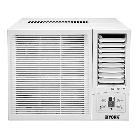
Summary of Contents for York Y9USC-09 B5R
-
Page 1: Service Manual
Window Y9USC/E 09 / 12 / 18 B5R SERVICE MANUAL Y9USC-09 B5R; Y9USE-09 B5R Y9USC-12 B5R; Y9USE-12 B5R Y9USC-18 B5R; Y9USE-18 B5R SM-Y9USC-E-09-18GB 03-07... -
Page 2: Table Of Contents
Service manual 1. Precaution ......................................2 1.1 safety Precaution....................................2 1.2 WARNING ......................................2 1.3 CAUTION ......................................2 1.4 FEATURES ....................................... 3 1.5 DIAGRAM PANEL..................................... 3 1.6 OUTSIDE DIMENSIONS .................................. 3 1.7 SPECIFICATION....................................4 2 INSTALLATION ....................................10 2.1 SELECT THE BEST LOCATION ..............................10 2.2 CHECK OFF INSTALLATION................................. -
Page 3: Precaution
Service manual 1. PRECAUTION 1.1 SAFETY PRECAUTION To prevent injury to the user or other people and property damage, the following instructions must be followed. Incorrect operation due to ignoring instruction will cause harm or damage. BEFORE SERVICE UNIT, BE SURE TO READ THIS SERVICE MANUAL AT FIRST. 1.2 WARNING 1.2.1 DO NOT USE DAMAGED POWER CORDS, PLUGS, OR A LOOSE SOCKET. -
Page 4: Features
To protect the compressor, please do NOT restart the unit in COOLING or HEATING mode in three minutes. 1.6 OUTSIDE DIMENSIONS Model A (mm) B (mm) C (mm) Y9USC-09 B5R Y9USE-09 B5R Y9USC-12 B5R Y9USE-12 B5R Y9USC-18 B5R Y9USE-18 B5R... -
Page 5: Specification
Service manual 1.7 SPECIFICATION Model Y9USC-09 B5R Y9USE-09 B5R Factory Model CE-KC26/E1N2 CE-KCR26/E1N2 Power supply Ph-V-Hz 1Ph , 220-240V~, 50Hz 1Ph , 220-240V~, 50Hz Capacity Btu/h 9000 9000 Input 1050 1110 Cooling Rated current Btu/w.h W/W 8.6,2.51 8.6,2.51 Capacity Btu/h... - Page 6 Service manual a.Number of rows b.Tube pitch(a)x row pitch(b) 21X13.37 21X13.37 c.Fin spacing Condenser d.Fin type (code) Hydrophilic aluminium Hydrophilic aluminium e.Tube outside dia.and type 7x0.25, innergroove tube 7x0.25, innergroove tube f.Coil length x height x width 370X315X40.11 370X315X40.11 g.Number of circuits Outdoor air flow (Hi/Mi/Lo) m3/h m3/h 700/620/540...
- Page 7 Service manual Model Y9USC-12 B5R Y9USE-12 B5R Factory Model CE-KC35/E1N2 CE-KCR35/E1N2 Power supply Ph-V-Hz 1Ph , 220-240V~, 50Hz 1Ph , 220-240V~, 50Hz Capacity Btu/h 12000 12000 Input 1420 1400 Cooling Rated current Btu/w.h W/W 8.5,2.48 8.6,2.51 Capacity Btu/h 12000 Input 1210 Heating Rated current...
- Page 8 Service manual a.Number of rows b.Tube pitch(a)x row pitch(b) 25.4X22 25.4X22 c.Fin spacing Condenser d.Fin type (code) Hydrophilic aluminium Hydrophilic aluminium e.Tube outside dia.and type 9.53x0.27, innergroove tube 9.53x0.27, innergroove tube f.Coil length x height x width 475X381X66 475X381X66 g.Number of circuits Outdoor air flow (Hi/Mi/Lo) m3/h m3/h 850/780/700...
- Page 9 Service manual Model Y9USC-18 B5R Y9USE-18 B5R Factory Model CE-KC46/E1N2 CE-KCR46/E1N2 Power supply Ph-V-Hz 1Ph , 220-240V~, 50Hz 1Ph , 220-240V~, 50Hz Capacity Btu/h 18000 18000 Input 2100 2100 Cooling Rated current Btu/w.h W/W 8.6,2.5 8.6,2.5 Capacity Btu/h 18000 Input 2000 Heating Rated current...
- Page 10 Service manual a.Number of rows b.Tube pitch(a)x row pitch(b) 25.4x22 25.4x22 c.Fin spacing Condenser d.Fin type (code) Hydrophilic aluminium Hydrophilic aluminium Ф9.53x0.27, innergroove tube Ф9.53x0.27, innergroove tube e.Tube outside dia.and type f.Coil length x height x width 560x406x44 560x406x66 g.Number of circuits Outdoor air flow (Hi/Mi/Lo) m3/h m3/h 1200/1100/1000...
-
Page 11: Installation
Service manual 2 INSTALLATION 2.1 SELECT THE BEST LOCATION 1. To avoid vibration and noise, make sure the unit is installed securely and firml. 2. Install the unit where the sunlight does not shine directly on the unit. If the unit receives direct sunlight, build an awning to shade the cabinet. -
Page 12: How To Drain
Service manual 2.3 HOW TO DRAIN The base pan ma overflow due to high humidity. To drain the excess water, remove the drain cap from the bottom of the unit (if fitted) and attach a drain hose (not supplied). 1. Take the drain pan which is packed with the unit. 2. - Page 13 Service manual 2.4.2 INSTALLATION OF THE UNIT INTO THE HOUSING Slide the unit into the housing until it is firmly against the rear of the housing. Care is required to ensure the foam sealing strips on the housing remain in position.
-
Page 14: Refrigerant Cycle Diagram
Service manual REFRIGERANT CYCLE DIAGRAM The figure below is a brief description of the important components and their function in what is called the refrigeration system. This will help to understand the refrigeration cycle and the flow of the refrigerant in the cooling cycle. -
Page 15: Operation Limits
Service manual 4 OPERATION LIMITS 4.1 COOLING OPERATION Outdoor unit air temp.ºC DB Indoor air temp. ºC DB Note: The chart is the result from the continuous operation under constant air temperature conditions. However, excludes the initial pull-down stage. 4.2 HEATING OPERATION Indoor air temp. - Page 16 Service manual SCHEMATIC DIAGRAM AND WIRING DIAGRAM Y9USC-09 B5R: Y9USE-09 B5R:...
- Page 17 Service manual Y9USC-12 B5R Y9USC-18 B5R: Y9USE-12 B5R Y9USE-18 B5R:...
-
Page 18: Troubleshooting
Service manual TROUBLESHOOTING In general, possible trouble is classified in three kinds. One is called Starting Failure which is caused from an electrical defect, another is ineffective Air Conditioning caused b a defect in the refrigeration circuit and improper application, and the other is called the Structure Damage. ROOM AIRCONDITIONER NAMEPLATE RATING MINIMUM... - Page 19 Service manual The compressor not to stop even the room Thermostat Check and replace if the thermostat is damaged. temp. has got to the setting temperature. Air filter Clean or replace if restricted. Vent. door Close if open. Unit undersized Determine if the unit is properly sized for the area to be cooled or heated.
- Page 20 Service manual Voltage Check voltage. Call Supply Authority if not within limits. Check the wire connections, if loose, repair or replace the terminal. If wires are off, Wiring refer to wiring diagram for identification, and replace. Check wire locations. If not per wiring diagram, correct.
- Page 21 wwwjohnsoncontrols.com SM-Y9USC-E-09-18GB 03-07...
Need help?
Do you have a question about the Y9USC-09 B5R and is the answer not in the manual?
Questions and answers