LG GR-T622 Service Manual
Hide thumbs
Also See for GR-T622:
- User manual (29 pages) ,
- Service manual (28 pages) ,
- Service manual (16 pages)

Related Manuals for LG GR-T622


Summary of Contents for LG GR-T622
- Page 1 REFRIGERATOR SERVICE MANUAL CAUTION BEFORE SERVICING THE UNIT, READ THE "SAFETY PRECAUTIONS" IN THIS MANUAL. MODEL: GR-T622/GR-T722...
-
Page 2: Table Of Contents
CONTENTS SAFETY PRECAUTIONS ............................... 2 SERVICING PRECAUTIONS..............................3 SPECIFICATIONS................................... 4 PARTS IDENTIFICATION ............................... 5 DISASSEMBLY..................................6-7 DOOR....................................6 DOOR SWITCH..................................6 THERMOSTAT ..................................6 FAN AND FAN MOTOR................................ 7 DEF' CONTROL ASM ................................7 LAMP....................................7 CONTROL BOX-R................................7 ADJUSTMENT..................................8 COMPRESSOR.................................. -
Page 3: Servicing Precautions
SERVICING PRECAUTIONS AIR RECHARGING IN COMPRESSOR vacuum operation is over, add the quantity in grams of R-134a to the refrigeration system. Remember that every Test the refrigeration system connecting it electrically before system has an exact quantity of R-134a with a tolerance of refilling operation. -
Page 4: Specifications
1. SPECIFICATIONS 1-1. Ref. No.: GR-T622DE ITEMS SPECIFICATIONS ITEMS SPECIFICATIONS DOOR DESIGN Side Rounded VEGETABLE TRAY Transparent Drawer Type DIMENSIONS (mm) 1732(W COMPRESSOR PTC Starting Type NET WEIGHT (kg) EVAPORATOR Fin Tube Type COOLING SYSTEM Fan Cooling CONDENSER Wire Condenser TEMPERATURE CONTROL Knob Dial REFRIGERANT... -
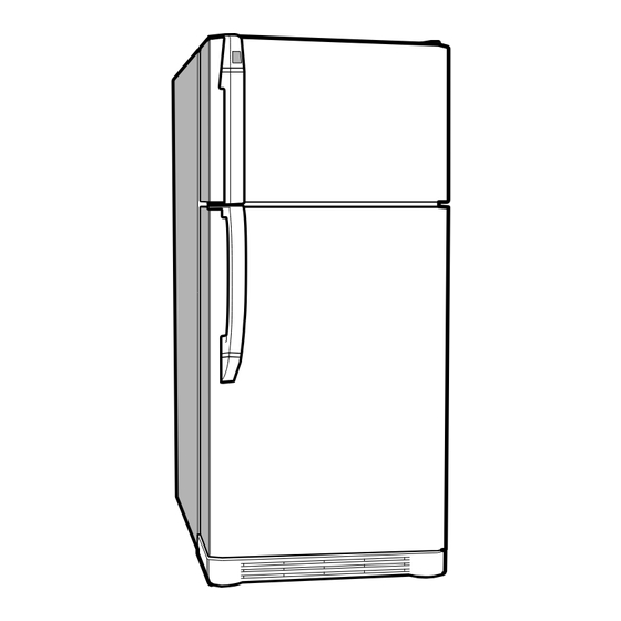
Page 5: Parts Identification
2. PARTS IDENTIFICATION FREEZER COMPARTMENT Freezer Shelf Automatic Ice Maker Lamp (Optional) and Ice Bank (Optional) Freezer Door Bin General Type Ice Tray (Optional) Door Cooling On the refrigerator door, Freezer Temperature the cold air passageway is Control Dial installed to supply cold air to the doorside of Temperature the refrigerator... -
Page 6: Disassembly
3. DISASSEMBLY 3-1 DOOR 3-2 DOOR SWITCH 1. To remove the door switch, pull out it with a '–' type Freezer Door 1. Remove the hinge cover by pulling it upwards. driver as shown in (figure 9). 2. Loosen hexagonal bolts fixing the upper hinge to the 2. -
Page 7: Fan And Fan Motor
3.4 FAN AND FAN MOTOR 3-6 LAMP 1. Remove the freezer shelf. (If your refrigerator have an FREEZER ROOM LAMP Ice Maker, disassemble the Ice maker first) 2. Remove the Grille by pulling it out and by loosening a screw. 3. -
Page 8: Adjustment
4. ADJUSTMENT 4-1 COMPRESSOR 4-2-3 PTC-Applied Circuit Diagram According to Starting Method for the Motor 4-1-1 Role The compressor intakes low temperature and low pressure gas evaporated from Evaporator of the Refrigerator, and OVERLOAD PROTECTOR(O.L.P) condenses this gas to high temperature and high pressure gas, and then plays delivering role to Condenser. -
Page 9: Olp (Overload Protector)
4-3 OLP (OVERLOAD PROTECTOR) CONTACTING 4-3-1 Definition of OLP POINT COVER (1) OLP (OVERLOAD PROTECTOR) is attached to the Compressor and protects the Motor by cutting the BIMETAL current to the Motor if the temperature rises and activates the bimetal spring in the OLP. (2) When over-voltage flows to Compressor motor, the CONTACTING POINT... -
Page 10: Troubleshooting
6. TROUBLESHOOTING 6-1 COMPRESSOR AND ELECTRIC COMPONENTS Remove the PTC- (Rating Voltage Power Source. Starter from the ±10%)? Compressor and measure the voltage between Terminal C of Compressor and Terminals 5 or 6 of PTC. OLP disconnected? No Voltage. Replace OLP. Check connection condition. -
Page 11: Ptc And Olp
6-2 PTC AND OLP Normal operation of Check another Separate the PTC- Observation value is Compressor is Starter from electric components. 220V/50Hz : 22§ ±30% Compressor and impossible or poor. 115V/60Hz : 6.8§ ±30% measure the 240V/50Hz : 33§ ±30% resistance between 127, 220V/60Hz : 22§... -
Page 12: Another Electric Component
6-4 ANOTHER ELECTRIC COMPONENTS Cooling is impossible Compressor Check if current flows to Cause doesn't run. the following components. Poor contacting and a. Thermostat gas leakage. b. Starting devices Shorted or broken. Poor contacting c. OLP or shorted. Coil shorted. d. -
Page 13: Service Diagnosis Chart
6-4 SERVICE DIAGNOSIS CHART COMPLAINT POINTS TO BE CHECKED REMEDY Cooling is • Is the power cord unplugged from the outlet? • Plug to the outlet. impossible. • Check if the power S/W is set to OFF. • Set the switch to ON. •... -
Page 14: Refrigerating Cycle
6-5 REFRIGERATING CYCLE Troubleshooting Chart TEMPERATURE STATE OF STATE OF THE CAUSE REMARKS OF THE THE SET EVAPORATOR COMPRESSOR PARTIAL Freezer room and Low flowing sound of A little high • Refrigerant level is low due LEAKAGE Refrigerator Refrigerant is heard and more than •... - Page 15 General Control of Refrigerating Cycle ITEMS UNIT STANDARDS PURPOSES REMARKS Pipe and Min. Pipe: within 1 hour. To protect The opening time should be reduced piping system Comp: within 10 minutes. moisture to a half of the standards during rain opening time Drier: within 20 minutes.
-
Page 16: Exploded View
8. EXPLODED VIEW & REPLACEMENT PARTS LIST The parts of refrigerator and the shape of each part are subject to change in different localities. 401A Capacitors and fuse are optional parts. 103B GR-T622, GR-T722 281A 301A : Option 281B 103A... - Page 17 : Option 200A 405C 330B 203A 405A 201A 205A 404A 329A 281E 332A 110C 212G 212C 205A 149A 212A 146A 149A 210A 125C 241B 125A 140A 140C 230A 140B 233A 231A 141A 141C 141B 140A 140E 281E 241A 140B 241C 140D 141A 141E...
- Page 18 P/No. 3828JD8291A MAY, 2000 Printed in Korea...
Need help?
Do you have a question about the GR-T622 and is the answer not in the manual?
Questions and answers