Table of Contents
Advertisement
Quick Links
Advertisement
Table of Contents

Related Manuals for Xblue Networks X-25


Summary of Contents for Xblue Networks X-25
-
Page 1: Installation Manual
X-25 Installation Manual XBLUE Networks Copyright ©... -
Page 2: Notifi Cations And Conventions
XBLUE Networks, LLC. The information contained herein is supplied without representation or warranty of any kind. XBLUE Networks, reserves the right, without notice, to make changes to the equipment, equipment design, and documentation as advances in engineering and manufacturing methods warrant, and assumes no responsibility and shall have no liability of any kind arising from the supply or use of this document or the material contained herein. -
Page 3: Ce Declaration Of Conformity
Windows Operating Systems 98/XP/NT/2000/ME/Windows7/Windows8 are registered trademarks of Microsoft Corporation. All other company, brand and product names, like Netscape Navigator ™ and Safari ™ are trademarks or registered trademarks of their respective owners. XBLUE™, XBLUE Networks ® , X-25™ Are all... - Page 4 WARNING 1. To avoid injury to yourself, or damage to the equipment, it is important to read and understand the installation instructions carefully before installing or powering up the system. 2. Unauthorized opening the server, the telephone or other associated equipment may cause damage to the equipment and yourself as well as voiding the manufactures warranty.
-
Page 5: Contents Of The Box
Box X-25 Telephone Server 6′ Ethernet Cable 47-9005 (8) Port Telephone Switch (4) Telephone Line Cables Quick Installation Guide Power Supply... -
Page 6: About This Manual
About This manual This manual was written to assist with the installation of the XBLUE X-25 System and is best used as a reference tool. We have done our best to describe all products and features as they actually work, but we apologize if the manual is incorrect in areas. -
Page 7: Table Of Contents
LAN ................................14 WAN ................................14 Client on your existing network ........................15 5 System Capacities ......................18 X-25 ....................19 6 LED Lights on the 7 System Specifi cations ....................21 8 Feature Description ......................25 Access Control - Browser .......................... 26 Account Code ............................ - Page 8 Table of Contents Busy Lamp Field (BLF) ..........................27 Call Abandon ............................. 27 Call Forward .............................. 28 Busy Call Forward ..............................28 Direct (Always) Call Forward ..........................28 Do Not Disturb Call Forward ..........................28 Follow me Forward ..............................28 Call Forking Call Forward ............................
- Page 9 Table of Contents Off Hook Preference ..........................33 One Touch Record ............................. 33 Outside Calls ............................. 34 Paging ............................... 34 All Call Page ................................34 Zone Page ................................34 Pause Insertion ............................34 Phantom Extension (Virtual) ........................34 Phonebook ..............................34 Private ...................................
- Page 10 Table of Contents 9 System Feature Codes ....................39 Agent Log on/off - UCD Group ........................42 Busy Callback ............................42 Call Forward .............................. 43 Call Forward - Internal ............................43 Call Forward - External ............................44 Call Forward - Call Forking ........................45 Call Forward - Follow Me ...........................
- Page 11 Table of Contents 11 Wireless Local Area Network (WLAN) ................ 75 Primary Wireless Network ......................... 75 Wireless - Additional Networks ........................76 Wireless Security ..............................77 WiFi Protected Setup (WPS) ..........................78 Wireless - MAC Filtering ........................... 79 Wireless Bridge ............................80 Wireless Advanced ............................
- Page 12 Management --> Access Control --> Passwords ....................133 Telephone Passwords ..........................133 Voice --> Phone --> Phone Extension ........................ 133 Hiding the X-25 ............................133 Management --> Access Control --> Service Port ....................133 Other important settings to change ......................134 Programming Tables ..........................
-
Page 13: Introduction
FAX machine. It will also support up to 16 SIP telephone endpoints. In addition, the X-25 includes all of the standard router features such as a Firewall, Local Area Network (LAN), Wide Area Network (WAN), plus an Integrated SIP server and 802.11 a, b, g, n wireless access, just to name a few. -
Page 14: Lan Vs Wan
LAN vs WAN The X-25 comes with one Local Area Network (LAN) and one Wide Area Network (WAN) port allowing it be installed as either a client or a server. The LAN port is only used when communicating to devices within the same local area, whereas the WAN can be used to communicate to local devices as well as devices over the Internet. -
Page 15: Client On Your Existing Network
The X-25can be installed in several different ways. As a client on your existing data network, as a standalone telephone system, or as the main data network. Client on your existing network When connecting the X-25 to your existing network, use only the Wide Area Network (WAN). The Cloud Router... - Page 16 Cloud Telephone Line providers as well. There are two ways of installing the X-25 as the edge device, one is to only use the WAN port and the other is to use both the WAN and the LAN ports.
- Page 17 Address. Notes: Connecting the X-25 WAN port to your existing network, or directly to your ISP, will give it direct access to the Internet. This will give you access to some advanced features such as email delivery and time synchronization.
-
Page 18: System Capacities
System Capacities Table 2.1 Maximum Confi guration PSTN Telephone Lines SIP (Cloud) Trunks SIP Extensions Single Line (Analog) (Telephone Lines) Telephone Extensions 4 Lines 4 SIP Trunks 16 Extensions 8 Telephone Lines 17 Extensions (16 SIP and Cellular and 1 Analog) Table 2.2 Physical System capacities Capacity Interface... -
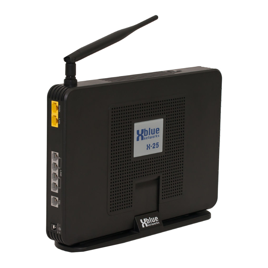
Page 19: Led Lights On The
X-25 LED Lights on the Table 2.4 LED Functions LED Name LED Color System Status Description Power is on and system is operational Power Blue Power and system is off Flashing The system is rebooting Wireless LAN initialization successful Wireless... - Page 20 Notes:...
-
Page 21: System Specifi Cations
System Specifi cations Table 3.1 System Specifi cation Feature Description Main Processor 400 MHz Dual Core MIPS Processor Broadcom BCM6369 Processor SDRAM External 64 MB Processor Flash ROM External 16 MB Supplementary Processor 1x DSP Mindspeed M82351 System Flash (Voice Mail) 512 MB Giga WAN PHY Chip Broadcom BCM5481... - Page 22 Table 3.5 Internet Protocol Protocol Documentation Description IP Address RFC 950 Defi nes the standards used to divide IP into Classes A, B and C using Subnets RFC 826, 3315 Address Resolution Protocol - Allows devices to fi nd a “Host” device using the network layer (MAC Address) RARP RFC 903...
- Page 23 Protocol Documentation Description RFC 793 Transmission Control Protocol provides the reliability that Internet Protocol (IP) does not, making it suitable for applications such as File Transfer and emails. Telnet RFC 2946 Telnet is a reliable connection-oriented transport protocol, which is Client/ Server Based.
- Page 24 Signalling Documentation Description RFC 791, 1060, The type of service octet is part of the Internet Protocol header that speci- 1122, 1123, fi es the priority of the attached datagram (message). 1195, 1247, 1248, 1349, 2474, 3168 ® DTMF RFC 4733 Dual Tone Multi-Frequency Tones - also known as touch tone - Defi...
-
Page 25: Feature Description
Feature Description Table 4.1 System Feature Description Table Feature Page Feature Page Access Control page 26 Least Cost Routing (Call Routing) page 32 Account Codes (Traveling COS) page 26 Line Group Assignment page 32 Alarm (Station) page 26 Live Call Record page 32 Alternate Attendant page 26... -
Page 26: Access Control - Browser
Alarm Each X-2020 connected to the X-25 system can be set to use up to three alarms, which can be programmed to play one time or set to always. The user can select between 11 (0 - 10) different ring tones. After the alarm is reached, it will play the programmed ring tone. -
Page 27: Automatic Daylight Savings (Ntp)
Automatic Daylight Savings (NTP) When the X-25 system is connected to the Internet it will automatically synchronize the date and time using Network Time Protocol (NTP). Therefore, when the time changes for daylight savings, the system will automatically change. Automatic Hold Automatic hold allows extension users to press a preprogrammed extension button known as direct station select (DSS) to announce a call without pressing hold fi... -
Page 28: Call Forward
Call Forward At default, all extensions are forwarded to voicemail. However, they can also use several other types of call forwarding such as; busy, direct, do not disturb, follow me, call forking, and Remote (External). These can be programmed using the web interface, which is easier, or by dialing the call forward code found on page Busy Call Forward Busy call forward, forwards all incoming calls to the forwarded destination only when the extension is busy. -
Page 29: Call Pickup Group
Call Pickup Group Any extension SIP telephone endpoint can dial star “ ” to pick up a telephone line that is ringing at a different extension. If multiple telephone lines are ringing the oldest ringing line will be accessed. Call Restriction When making a telephone line call all digits dialed will be compared to the telephone’s Class of Service and Restriction Table. -
Page 30: Call Waiting
Call Waiting While on a call with the X-2020 telephone you can be alerted to a second call. In the display, you will see the second call, and have the ability to pick up the call or let it forward to voice mail. This feature will not work if your telephone is busy forwarded. -
Page 31: Telephone Line
Simple Mail Transport Protocol (SMTP) to send the vocemail message as a standard “WAV” fi le, which can be reviewed by most smart phones or multimedia personal computer. This requires the X-25 system to have its own Email address, such as voicemail@YourCompany.com. -
Page 32: Flexible Numbering Plan
See Call Routing Line Group Each telephone line in the X-25 is assigned to one of four trunk groups, which are used to group similar trunks together. For example, all PSTN lines in group 1 and SIP Trunks in group 2. -
Page 33: Meet Me Page
Mutual (Group) Mailboxes The X-25 uses Virtual Mailboxes as special mailboxes that can appear on multiple telephone extensions. This allows a group of extensions users to share access to the same mailbox. When a new message is left in the mailbox, all extensions with a programmed button of that virtual mailbox will light, indicating that there is a new voicemail message. -
Page 34: Outside Calls
Outside Calls Once Authenticated, and X-2020 telephone can dial without going off hook, pressing the speaker button, or accessing a telephone line. In addition, the user can press the softkey under “Backsp” to delete an incorrectly dialed telephone number. Once the “Dial Time-out” timer expires (default 5 seconds), or the user press “Dial” under the display or the center navigation key (Check) the call is sent to the system for processing. -
Page 35: Redial
Redial Also known as Last Number Redial or Call Log, allows you to select previously dialed, received or missed telephone numbers by selecting them from a list stored on the X-2020 telephone. Registration Server The system is equipped to act like a registrar server for both telephone end points and SIP trunks, which eliminates any possibility of a numbering confl... -
Page 36: System Time And Date
System Time and Date When connected to the Internet the system uses Network Time Protocol (NTP) to synchronize the time and date. In addition, the date and time can be set manually. Time and Date in Display The fi rst line on the LCD of the idle X-2020 telephone shows the date and time. The time format can be changed from the default, “USA Time 12 Hour”... -
Page 37: Ucd Reroute
UCD Reroute All UCD groups have the ability to reroute unanswered calls to an automated attendant menu greeting, voice mailbox, or physical or virtual extension. If required, a mailbox can be programmed as an announcement only, which will play a message and then disconnect the call. Virtual Extension (Phantom) There are sixteen (16) special virtual extensions, which are actually a mailbox and not an extension, are used for personnel that need a presence but not a physical telephone, such as outside salesmen. - Page 38 Notes:...
-
Page 39: System Feature Codes
System Feature Codes Feature Programming Sequence Page Browser Agent Logon/Logoff Log on *91 page 42 Log off **91 Busy Callback Call Ext Dial 6 page 42 Cancel *66 Call Forward - Call Forking (requires a *26 + t + Ext page 45 SIP Trunk) 0 = ICM... - Page 40 Feature Programming Sequence Page Browser Call Forward - Follow me *25 + t + Ext + * + pswd page 46 This is programmed from the new extension 0 = ICM 1 = Outside 2 = Both Ext = Extension Number pswd The voicemail password Default is 4 zeros (0000)
- Page 41 Feature Programming Sequence Page Browser Extension Feature Reset *69 + Extension or Administrator page 49 Password Feature Button Programming *70 + BN + FT page 49 These parameters may be easier to BN = program through the GUI Button number Telephone 01~04 Sidecar 05~28 FT =...
-
Page 42: Agent Log On/Off - Ucd Group
Agent Log on/off - UCD Group • * 91 - Agent Log on • ** 91 Agent Log off Description: An extension programmed into a UCD group is considered an Agent. At times, such as Lunch, an agent will want to log out of a UCD group. When they return they will want to log back into the group. Operation: While idle, dial **91 to log out off the group for a break, then *91 to log back into the Group. -
Page 43: Call Forward
Call Forward There are four different types of call forwarding; Always (direct), Busy, No Answer and DND, each call can be forwarding to an internal extension physical or virtual, voicemail, UCD, or to an external telephone number such as a cellular telephone. This allows the user to customize how calls to their extension will forward. In addition, intercom and telephone line calls can be programmed to go to the same or different locations. -
Page 44: Call Forward - External
Call Forward - External External Call forward allows you to forward your extension to an external telephone number. This will require one incoming and one outgoing telephone line to complete this operation. The call, once forwarded are monitored by the FXO to FXO Call Duration time, which, at default, is set to 5 minutes. Operation: Call Forward - External * + CFW + t + * + pswd + * + Outside Number... -
Page 45: Call Forward - Call Forking
Call Forward - Call Forking Description: This feature will allow a transferred telephone line or intercom call to ring at two simultaneous destinations, such as an extension (LAN/WAN) or a cellular telephone. When one party answers the call both stops ringing. *** When Call Forwarding - Call Forking is used to an external number requires a SIP Trunk! Operation: To activate:... -
Page 46: Call Forward - Follow Me
Call Forward - Follow Me Follow me forward allows the user to use a different telephone extension and still receive their calls. Go to the new location and enter the following information. Don’t for get to dial the “*” before the password or the enter will not work. -
Page 47: Call Park
Call Park Call park, often referred to as “Putting a call into Orbit” allows extension users to place a call into a special holding area that can be retrieved by any other extension in the system by dialing the Park Answer Code. Operation: While on a telephone line call, the extension presses a preprogrammed call park button to park the call. -
Page 48: Class Of Service - Traveling
Class of Service - Traveling This feature allows the user to roam from one extension to another and retaining their dialing privileges, regardless of the telephone’s programmed Class of Service Operation: When making a call from a telephone extension with a more restrictive class of service, enter *55 + Your extension number + Your voicemail password, default is 4 zeros (0000). -
Page 49: Extension Feature Reset
Extension Feature Reset This feature is a quick way to deactivate several features that have been changed from factory default. Operation: From the extension dial *69 + The extension’s voicemail password or the administrator password The following will be set back to factory default: •... -
Page 50: Feature Button Reset
Programming Buttons - Example Table 5.2 Call Park on Button 4 BN Program Code BN Number Call Park Park Location Entry *710403731 Table 5.3 Agent Log On/Off on Buttons 3 and 4 BN Program Code BN Number Feature Log on/off codes Entry *91 (Off ) *700304*91... -
Page 51: Paging Allow/Deny
Paging Allow/Deny This feature allows the user to enter a code to allow or deny paging at their extension. Operation: To enable paging deny (to block paging at your extension) dial *99 To disable paging deny (to allow paging at your extension) dial **99 Notes: Phone Lock/UnLock The phone Lock/Unlock feature allows the user to lock their extension to prevent someone from making... - Page 52 Notes:...
-
Page 53: Programming
This will bring up the Login window The User name to log into the X-25 system is admin2583 and the password is admin plus the last 6 alphanumeric characters of the systems MAC Address. The MAC Address can be found on the back of the system (see the label below) and is written, xx.xx.xx.xx.xx.xx. -
Page 54: Programming Parameters
Programming Parameters There are eight major sections that make up the programming parameters of the X-25 system. Two sections, “Device Information”, which shows the current networks’ status and “Diagnostics”, which shows the status of the WAN/LAN, Standard PSTN and SIP IP telephone lines, the automated attendant ports, and the FXS, Analog (SLT) port, both are for information only. -
Page 55: Device Info
“Device Info” Device Info The Device Info page shows the software and hardware versions as well as the LAN and WAN port, IP address and the date and time. Summary Page The summary page shows information about the device, including software and hardware versions, MAC Address and how long the system has been on line and operational. -
Page 56: Statistics Pages
“Device Info” Statistics Pages The Statics pages show the amount of data received and transmitted on both the LAN and the WAN ports of the system. This is information can be very helpful for troubleshooting the system. -
Page 57: Route
“Device Info” Route The Route table shows the destination, Gateway and Subnet Mask, as well as the Flag, and different devices on the network. The Flag column shows the status of each device. Flags Meaning The device is up and operating The device is Rejected This defi... -
Page 58: Arp
“Device Info” The Address Resolution Protocol (ARP) table is where the system catalogs the IP Address of a device with its physical hardware (MAC) address. In addition, this page shows which device (LAN or WAN) is using the specifi c IP Address. -
Page 59: Dhcp Server
“Device Info” DHCP Server When using the LAN port, the system can be used as your main router allowing computing devices to automatically be assigned an IP Address. When set this way, the system becomes your network’s Dynamic Host Confi guration Protocol (DHCP) server, otherwise this table will be empty. -
Page 60: Advanced Setup
“Advanced Setup” Advanced Setup WAN Page At default the WAN port is set to automatically connect to your existing network using Dynamic Host Control Protocol (DHCP). Your existing router will assign, known as lease the WAN port an IP Address, Subnet Mask, Default Gateway as well as a primary and secondary DSN Servers. -
Page 61: Static Ip Settings
“Advanced Setup” Static IP Settings Select Advanced Setup WAN, and make a note of all information under “Network Type” and then using the drop down menu Select “Static IP”. Enter the Static IP address, from your ISP, or from your existing Network. Once the information is entered, press Save and Reboot. -
Page 62: Pppoe
“Advanced Setup” PPPoE You may need to authenticate to your ISP with a user name and Password, which is known as Point-to- Point over Ethernet (PPPoE). In this case, using the drop down menu, you will select PPPoE, and enter the Information provided to you by your ISP. -
Page 63: Local Area Network
“Advanced Setup” Local Area Network At default, the LAN is set as a DHCP Server and will automatically assign an IP address of 192.168.10.x to any device connected to the LAN port. The DSP IP Address - must be unique! If there are any confl icts, with this IP Address, the system will not function correctly. -
Page 64: Network Address Translation
“Advanced Setup” Network Address Translation Network Address Translation (NAT) is designed to allow external devices access the internal devices located on your Local Area Network (LAN). In addition, it is used to “punch holes” in the Firewall, if it is Enabled. The system uses three different types of NAT, Virtual Server, Port Triggering and DMZ. - Page 65 “Advanced Setup” Port Triggering Port Triggering allows you to grant one or more ports access, called Punching a hole, through the Firewall. The Firewall’s job is to block unauthorized access to your network. In addition, some applications, such as AOL aim, uses one port while being processed over the Internet, but a different one while on the LAN.
- Page 66 “Advanced Setup” DeMilitarized Zone - known as a DMZ, allows an internal device, such as a client computer, to be seen on the Internet. Basically, information from the WAN (outside) is sent to a server with a fi rewall, which evaluates the information.
- Page 67 “Advanced Setup” Simply enter the IP address of the internal device that you would like to appear as though it were directly on the Internet.
-
Page 68: Security
“Advanced Setup” Security Security, not to be confused with “Wireless Security” (for wireless security see page 77), is used to block incoming and outgoing IP addresses as well as a “Parental Control” settings. Incoming and outgoing fi lters are used to direct specifi c packets to the programmed location based on a set of parameters. -
Page 69: Parental Control
“Advanced Setup” Parental Control Also, know as Administration Control, this feature allows you to identify specifi c devices to allow or deny access to the Internet. There are two areas of Parental Control, Time Restrictions, which limits the time of day and day of week that a device can access the Internet, and the other allows or denies specifi... - Page 70 “Advanced Setup” URL Filter You may block (Exclude) or allow (Include) up to 200 specifi c URL addresses. Any computing device on the LAN side will be governed by the rules of these two tables. Notes: There are 100 include, and 100 exclude entries, for a total of 200.
-
Page 71: Quality Of Service
Therefore, XBLUE Networks will do its best to help with voice quality but there is no guarantee, written or implied, that the quality of the voice network will be satisfactory, without changing network devices or upgrade available bandwidth, at the owner’s expense... -
Page 72: Routing
“Advanced Setup” Routing Routing, also know as Static Routing, is used to establish IP packet routing without requiring the devices to communicate with each other. This is considered a “No Fault” network, because there is no way for the network to recover in the event failure. -
Page 73: Dynamic Dns
DNS server, allowing the IP address to change without disrupting service. The X-25 is preprogrammed to use DyDNS’s paid service allowing you to use a non-static IP Address when connecting to the X-25 remotely and when using remote telephones. - Page 74 “Advanced Setup” Universal Plug and Play (UPnP) Universal Plug and Play is a set of protocols created specifi cally to allow devices on a peer to peer network, generally using either TCP port 5000 or UDP port 1900, to connect seamlessly and simplify their implementation.
-
Page 75: Wireless Local Area Network (Wlan)
The system also has three Guest Accounts, also known as Hot Spots, which are only active when the primary network is enabled. The third is preprogrammed for XBLUE Networks’ WiFi devices. Because wireless networks broadcast their names, it is a good idea to use a name that is nondescript, and well secured. -
Page 76: Wireless - Additional Networks
Two of the three guest accounts are disabled, but can be quickly enabled by clicking in the check box. The third is preprogramamed for XBLUE Networks Wireless devices. Note: If the Primary wireless is disable, all of the guest hot-spots will also be disabled. -
Page 77: Wireless Security
If you are connecting the system to your existing network that already has wireless you may want to disable the WLAN completely. The XBLUE Networks Universal Wireless Adapters can be reprogrammed to connect to your current wireless network, or to make it even easier, you could reprogram your router to match the third... -
Page 78: Wifi Protected Setup (Wps)
“Wireless Local Area Network (WLAN)” WiFi Protected Setup (WPS) The system comes with WiFi Protected Setup (WPS), which like Bluetooth, requires the device to be paired with the system. Once paired, the two devices will automatically reregister each time the two devices are in the same location. -
Page 79: Wireless - Mac Filtering
“Wireless Local Area Network (WLAN)” Wireless - MAC Filtering The system also allows you to further secure your Wireless LAN using MAC Filtering. You can enter only the allowed devices, or you can deny specifi c devices. Notes: Locating a device’s MAC Address: Usually, the MAC Address can be found on a label, which is affi... -
Page 80: Wireless Bridge
“Wireless Local Area Network (WLAN)” Wireless Bridge The system can be set as an Access Point or a Wireless Bridge. A wireless access point allows other devices to access the wireless network. Whereas a Wireless Bridge, bridges two wireless sections of a network and also allows wired access to both sides of the connection. - Page 81 “Wireless Local Area Network (WLAN)” The Wireless Bridge At default, the system is set to access point. Unless you are using it as a wireless bridge, this parameter should remain set to Access Point.
-
Page 82: Wireless Advanced
The system is set up to accommodate the most common settings in the United States. Generally these settings will not need to be changed. Note: Changing these settings may cause erratic operation. Only change these settings if you are instructed to by XBLUE Networks technical support or other networking professional. -
Page 83: Station Info
“Wireless Local Area Network (WLAN)” Station Info Station Info is a reference only page that shows any authenticated wireless clients and their status. -
Page 84: Power Saving
“Wireless Local Area Network (WLAN)” Power Saving The Power Saving feature gives you the ability to automatically enable and disable the Wireless LAN once in a 24 hour period of time. -
Page 85: Xblue Universal Wifi Adapter
XBLUE Universal WiFi Adapter Because there is not always an Ethernet port where you want to put your telephone, XBLUE Suggests their Universal WiFi Adapter, which will automatically connect to your X-25 system and does not require additional programming. Note: The quality of your wireless connection may affect the quality of the voice connection. - Page 86 Notes:...
-
Page 87: Voice
Voice The Voice area of programming is used to establish the system numbering plan, dial codes, service mode, answering position, call routing and restriction and other telephone system parameters. There are seven programmable parameters within the Voice programming directory; Phone, Trunk, System, Voicemail, NAT Transversal, Diagnostics and Registered Phone, which makes up most of the telephone system parameters. - Page 88 555-1212, then that is what you would enter, if you normally dial 913-555-1212, then that is what you would enter. Display Name The display name will be referenced after the telephone is authenticated. This is used with the X-25 soft telephone MAC Binding The X-25 system uses the telephone’s MAC address to ensure that the correct device is registered and...
- Page 89 “Wireless Local Area Network (WLAN)” Programmable Keys The Keys on the X-2020 Telephones can be reprogrammed using a standard Internet browser. These buttons can be programmed at each extension or you can “Push” (send the parameters to all extensions at the same time).
-
Page 90: Trunk
Service) ports which are analog lines that are usually connected to a traditional telephone line provider, such as home telephone Lines. In addition, the X-25 has the ability to authenticate up to four “Cloud” telephone lines, such as XBLUE Cloud’s low cost premium quality telephone lines, using Session Initiated Protocol (SIP) known as SIP Trunks. -
Page 91: Sip Trunks (Telephone Lines)
“Wireless Local Area Network (WLAN)” SIP Trunks (Telephone Lines) The X-25 comes equipped to support four Cloud Telephone Lines known as “Trunks”, and up to forty Private Lines, known as Direct Inward Dial (DID) numbers. Unlike standard PSTN lines these lines are not physically connected to your system they connect by authenticating over your broadband Internet connection. -
Page 92: Direct Inward Dialing
“Trunk Group” page. Depending on your SIP IP Trunk provider and the X-25 system programming may restrict what Outgoing Caller ID can be sent. Ideally, if your DID rings directly to an extension, you can defi ne the Outgoing Caller ID as the... -
Page 93: Trunk Group
Trunk Group The X-25 system has four trunk groups, each supports one or more telephone lines. Trunk groups are used to group trunks that are used in similar ways, such as local and long distance calling. At default, all of the “PSTN”... -
Page 94: Answer Position
“Wireless Local Area Network (WLAN)” Answer Position Answer Position also known as Ring Assignment, is where you defi ne where each telephone line will ring into the system. Each line can be programmed to ring differently during the day and the night. Using the drop down menus, select which line to program, and then select where it should ring during the day, and night. -
Page 95: Call Routing (Rules)
“Wireless Local Area Network (WLAN)” Call Routing (Rules) Call Routing is a set of “Rules” that you can set to automatically route dialed calls to a specifi c telephone line or line group. The rule will only be followed if all aspects of the rule are “True”, otherwise it is ignored. Enter the information that will make up the rule and press “Add”. - Page 96 “Wireless Local Area Network (WLAN)” Note: For proper operation of redial, or using the dialed, missed, and received call logs, you may need to establish a rule for your home area code, which can be used to insert or delete specifi c digits. The system accesses the rules sequentially, when a match is found, the call placed.
-
Page 97: Call Restriction Rules
Call Restriction is a table of rules that allows the administrator to enter up to 13 digits, which when dialed can be allowed or denied. The X-25 system allows the administrator enter each rule and select which table, Allow or Deny will be referenced when a number is dialed. -
Page 98: Routing Emergency Numbers
“Wireless Local Area Network (WLAN)” Routing Emergency Numbers You may enter up to 5 emergency numbers that can be dialed regardless of Call Routing, Toll Restriction or Class of Service. -
Page 99: System
You may select between 2, 3 and 4 digit extension numbering plans. The last number will be the FXS, which is the port labeled “TEL” on the X-25 system and supports a standard cordless telephone. The numbers entered cannot confl ict with any other sequence of numbers. For example, you could not set the numbering plan to 400 without changing the All Paging Number fi... - Page 100 “Wireless Local Area Network (WLAN)” Operator Code At default when you dial zero (0) you will ring extension 101 both day and night. To change this click, on Operator Code and you can select the same or different Operators for day and night. In addition, if the defi ned operator is busy on a call, you can device an alternate day and night operator.
-
Page 101: Service Mode
“Wireless Local Area Network (WLAN)” Service Mode The system can run one of three different modes; Day, Night or Timed. While in the Day mode, calls will ring into the day ringing location, the day Auto Attendant outgoing message (greeting) will play, and the Day Class of Service will be applied to extensions’... -
Page 102: Transmission
The Transmission area of programming allows you to customize the low-level settings of the telephone system. These parameters are preset by the country that the system is installed and are usually not changed. Only change these parameters if you are on the line with an XBLUE Networks Technical Support or other qualifi ed telephone technician. -
Page 103: Smdr
“Wireless Local Area Network (WLAN)” SMDR Station Message Detail Recording (SMDR) can be enabled to create a log of incoming and outgoing calls that can be reviewed. You may highlight the list, copy and paste it into an spreadsheet application. UCD Call Log This is a list of calls that were received, but not answered, into one or more of the UCD Groups. -
Page 104: Voicemail
Generally, an Auto Attendant will offer you a list of choices, known as menu options, such as, “For sales press 1, for Support press 2...etc., In the X-25 system, this function is called “Single Digit Dialing” and is found on the “General Voicemail Page”. Each menu has fi... -
Page 105: General Settings
• RTP Packet Size - At default this is set to 20 milliseconds and is adjustable from Dynamic, 10 - 60, but should remain set to 20 unless otherwise instructed by an XBLUE Networks Technical Support Engineer. • DISA - Direct Inward System Access - This feature, when enabled, allows inbound callers to enter a code and gain access to system features such as outbound calling. - Page 106 Email Delivery of a voicemail message The X-25 system requires its own email address, such as voicemail@yourcompany.com in order to email a message. You will then enter the same information that you would enter in an email client such as outlook or your smart telephone.
-
Page 107: Phone Extension
“Voicemail” Phone Extension Enter the “First” and “Last” name of the user of each mailbox. These names are used if “Dial By Name” is enabled. In addition, each extension must record their “Name” to place the name in the dial by name function. •... -
Page 108: Virtual Extension
Virtual Extension The X-25 can have up to 16 virtual or phantom extensions, which are used for employees that do not have a physical telephone, but want to have a mailbox on the system. Once a virtual number is assigned you can dial it directly, transfer calls directly to the mailbox, and it can be used as an answer position and even DID Routing extension. -
Page 109: Update Moh File
“Voicemail” Update MOH File The X-25 comes with Music on Hold, which is played to callers that are placed on hold. You can change this fi le by uploading a mono “WAV” fi le, which is a maximum of 5000K. -
Page 110: Holiday Settings
“Voicemail” Holiday Settings This allows you to preprogram up to 20 different dates to play a special holiday greeting. The holiday greeting will only play when the dates match the entry, after that date, the appropriate day or night greeting will begin playing automatically. -
Page 111: Advanced
“Voicemail” Advanced This feature opens a FTP connection, if enabled, between the Personal Computer and the X-25 system. WARNING - Any changes made with this page may result in erratic operation. DO NOT make any changes unless instructed to do so by an XBLUE... -
Page 112: Nat Traversal Confi Guration
“Voicemail” NAT Traversal Confi guration Network Address Traversal (NAT) is used to allow remote telephones to register to your X-25 even when it is behind a fi rewall or another router using NAT. -
Page 113: Management
Click on “Backup Settings” and save the fi le in a location that is easy to fi nd, such as \\X-25 Backups\. It is also a good idea to use a sequential numbering scheme such as 1-1-2015 BackupSettings.tar. -
Page 114: Update
“Wireless Local Area Network (WLAN)” Update This parameter is used to upload a previous system backup Restore Default Most commonly used for troubleshooting, the restore default sets the system back to factory default. The system can be reprogrammed manually or upload a previous backup. There are three areas of programming that can be defaulted, Just the Settings, Just the voice prompts, or the whole system. -
Page 115: System Log
“Wireless Local Area Network (WLAN)” System Log The system log is used to verify and diagnose networks settings and errors. There are several different levels of system logs from, “Informational to Critical”. Generally, a technical support engineer will ask you to enable this parameter for troubleshooting. -
Page 116: Tr-069
“Wireless Local Area Network (WLAN)” TR-069 TR-069 is the protocol for Wide Area Networks (WAN) Management which defi nes the auto confi guration of a server. This is not currently used. -
Page 117: Time Settings
“Wireless Local Area Network (WLAN)” Time Settings Using the WAN Port the X-25 has the ability to synchronize the date and time with up to fi ve different time servers, and it can be set to use automatic daylight savings time rules. -
Page 118: Daylight Savings Time
“Wireless Local Area Network (WLAN)” Daylight Savings Time The system, at default, is set to automatically adjust for daylight savings time. Or you can set so that you can change it manually. -
Page 119: Access Control
“Wireless Local Area Network (WLAN)” Access Control The port, how or where a system can be accessed, specifi c IP address and changing passwords are all parameters that are set in Access Control. Service Port At default the system uses commonly used ports for the Web, FTP, TFTP, Telnet and SSH parameters. Since these are “Virtual”... -
Page 120: Services
“Wireless Local Area Network (WLAN)” Services Services Access is used to help secure the system by allowing or denying which service will be available for the LAN or the WAN ports. The LAN port is enabled for FTP, HTTP and ICMP, all other parameters can be enabled by checking or disabled by unchecking the parameter. -
Page 121: Access Control - Ip Address
“Wireless Local Area Network (WLAN)” Access Control - IP Address To further secure your system, you may enable IP Address, which will validate the IP Address of any device trying to enter programming in your system. If the IP Address is not listed, the attempt will be rejected. -
Page 122: Password
“Wireless Local Area Network (WLAN)” Password The system has 3 passwords; “admin2583” and “support” which both have administrative rights and “user” which has limited rights. All passwords should be changed as soon as the system is installed and operational. For security reasons, the password for your system is tied to the system’s MAC address. The MAC address can be found on the label on the back of the system. -
Page 123: Ptc Confi Gure
“Wireless Local Area Network (WLAN)” PTC Confi gure You can confi gure PTC in this page to support device fi rmware and confi guration fi le, phone fi rmware updating. -
Page 124: Update Software
“Wireless Local Area Network (WLAN)” Update Software XBLUE Networks may, occasionally put new version of software on their website. Locate and download the software and save it on your local computer’s hard drive, in a location that the can be easily found. To check for new software go to http://xbluenetworks.com/x25-support.html... -
Page 125: Upgrade Phone Software
“image” to the system. XBLUE Networks may, occasionally put new version of software on their website. Locate and download the software and save it on your local computer’s hard drive, in a location that the can be easily found. To check for new software go to http://xbluenetworks.com/x25-support.html... - Page 126 “Wireless Local Area Network (WLAN)” Update APNS Certifi cation - This feature, not currently used in the X-25 system, is used when connecting the system to a 3G or 4G Cellular Network.
-
Page 127: Reboot
“Wireless Local Area Network (WLAN)” Reboot The reboot page allows you to reboot the system from anywhere that you can connect to the system. -
Page 128: Diagnostics
“Wireless Local Area Network (WLAN)” Diagnostics The diagnostics page is a view only page that gives you the status of your network connections, PSTN and SIP Trunk Lines, Automated Attendant, and the FXS port. -
Page 129: Voicemail Operation
“Voicemail Usage” Voicemail Operation Getting to know your voicemail When the X-2020 telephone is connected to the system it can access voicemail by pressing the message button, which is the button with an ICON of an envelope. When a new message arrives, the light above the display will begin fl ashing and then display will show an envelope with the new message count. -
Page 130: Setting Up Your Voice Mailbox
“Voicemail Usage” Setting up your Voice mailbox It is a good idea to customize your voice mailbox when you begin working with your new telephone system. To do this you will press your message button and you will be prompted to enter your password. The default password is four zeros (0000). - Page 131 “Voicemail Usage”...
-
Page 132: Voicemail Administration
“Voicemail Usage” Voicemail Administration Any mailbox can log into the administration mailbox to record the main system greetings. The automated (receptionist) attendant can answer with one of ten (10) menus, each with fi ve different greetings; Day, Lunch, Night, Holiday and Temporary. To log into the administration mailbox, fi... -
Page 133: System Passwords
The default password consists of the word “admin or support” plus the last 6 alphanumeric characters of the system’s MAC Address, which can be found on the back of the X-25 system. For example, for the login admin2583 password admincecde4, all lower case, or the login support password supportcecde4. New passwords can be up to 16 alphanumeric characters;... -
Page 134: Other Important Settings To Change
Other important settings to change Advanced Settings --> WAN Enable Firewall Wireless --> Basic --> Primary Change the SSID – Do not use your company name – use a hobby like fl yfi shing and then click on Hide Access Point so that it is not visible to everyone that is looking for Wireless connections. Wireless -->... - Page 135 Once you have completed this procedure it is a good idea to create a back up that includes the new settings. Advanced Settings --> Upnp Uncheck “Enable Upnp protocol”. Thus disabling the telephones ability to automatically register to your X-25. To create a backup of your new database: Management -->...
-
Page 136: Programming Tables
Programming Tables Management Access Control Passwords Default Password New Password Last 6 of the MAC address Login Name – admin2583 (lower case) Last 6 of the MAC Address Login Name – support (lower case) Login Name – user user Management Access Control Service Port Web Port... - Page 137 Voice Phone Phone Extension Voice Voicemail Phone Extension Confi guration Passwords to change Phone Extension Voicemail Wireless Mac Filter – Enter the MAC Addresses of all Wireless Devices Device MAC Address i.e. 00:19:15:CF:BC:58...
- Page 138 Voice Trunk Call Routing From Insert Destination Entered Area code 1 Group 1 Area Code 1 Group 1 1200 1899 Group 1 Group 4 Group 4 Group 1 Voice Trunk Call Restriction From Trunk Access Table Type Entered Deny...
-
Page 139: Scope
Scope: The X-25 comes standard with a single Music on Hold song, which is played to callers that are Parked or put on hold. To further customize your X-25, you may upload a diff erent song or create a special message to be played while callers are on hold. -
Page 140: Goldwave
Goldwave Launch Goldwave Then go to “File” --> “Open” and locate the fi le that you want to use. Then Select “File”, “Save As” – PCM Signed 16 bit, Mono... - Page 141 Then update the display to show the new “Mono” fact Then go to “Eff ect” and select “Resample” and using the dropdown menu select “8000”...
- Page 142 Then go to “Eff ect” and select “Volume” “Change Volume” – Using the drop down menu, select “Half” and then press “OK” The Track will now be narrower, thus the fi le has a lower volume Select – “File” and then “Save” – Locate the fi le to verify that it is 5,000K or less. If the fi le is more than 5,000K you will need to “Trim”...
-
Page 143: Audacity
Audacity Launch Audacity and go to “File” then “import” - Audio File. Then locate and double click on the desired fi le. Go to “Tracks” and select “Stereo to Mono” To change the sampling rate, locate the “Project Rate (Hz)” in the lower left and change it to 8000. - Page 144 To lower the volume, locate the volume slide and slide it to the left. Once you are happy with the fi le, save it by going to: File, Export and export it as a “WAV (Microso ) signed 16 Bit PCM – fi...
- Page 145 Locate the fi le to verify that it is 5,000K or less. If the fi le is more than 5,000K you will need to remove part of the song. To do this, click and hold the mouse bu on down in the track and then slide the mouse, highligh ng the area to be re- moved.
-
Page 146: File Name And Upload
Log into the X-25 and go to “Voice” “Voicemail” “Update MOH File” Click Browse – and locate the mohpcmu.wav fi le Check Upload File You will need to reset your X-25 by unplugging it, wai ng 5 seconds and plugging it in again. - Page 147 Notes:...
- Page 148 X-25 Installation Manual XBLUE Networks, LLC © Copyright...
Need help?
Do you have a question about the X-25 and is the answer not in the manual?
Questions and answers