
Related Manuals for Fanimation The Embrace FPS7967 series


Summary of Contents for Fanimation The Embrace FPS7967 series
-
Page 1: Ceiling Fan
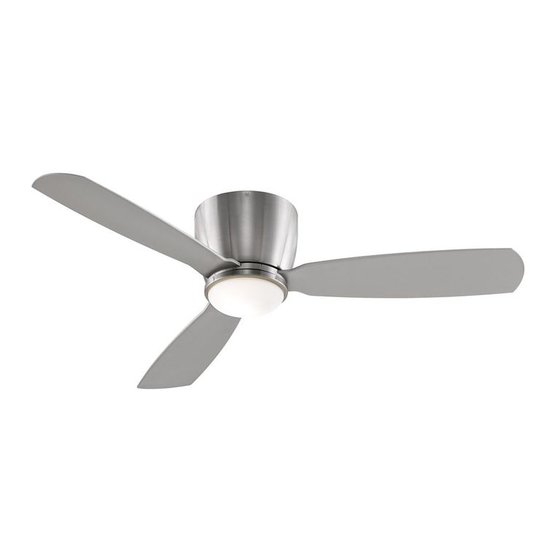
The Embrace ™ Ceiling Fan FPS7967** 44” Net Weight 23.68 lbs (10.74 kg) FPS7967** 52” Net Weight 23.68 lbs (10.74 kg) Model No. FPS7967** OWNER’S MANUAL READ AND SAVE THESE INSTRUCTIONS... -
Page 2: Important Safety Instructions
Fanimation. 7. Fanimation reserves the right to modify or discontinue any product at any time and may substitute any part under this warranty. 8. Under no circumstances may a fan be returned without prior authorization from Fanimation. The receipt of purchase must ac- company authorized returns and must be sent freight prepaid to Fanimation. -
Page 3: Table Of Contents
Table of Contents Unpacking Instructions................4 . -
Page 4: Unpacking Instructions
– Four Wire Connectors Fanimation. Substitution of parts or accessories not designated for use with this product by Fanimation could – 4 result in personal injury or property damage. Contact your retail store for missing or damaged parts. -
Page 5: Electrical And Structural Requirements
8 - 9 feet above the floor for optimal airflow. Consult your down into the occupied space.Remember to adjust your Fanimation Retailer for optional mounting accessories. thermostat when using your ceiling fan - additional energy and dollar savings could be realized with this simple step! Turn Off When Not in the Room Ceiling fans cool people, not rooms. - Page 6 Electrical and Structural Requirements (Continued) No blocking (Figure 3) Paired with a deep box, this hanger is meant to span CEILING JOIST between two joists and takes the place of wooden blocking. WARNING To reduce the risk of fire, electrical shock, or personal injury, mount fan to outlet box marked acceptable for fan support of 15.88 kg (35 lbs) or less.
-
Page 7: How To Hang Your Ceiling Fan
How to Hang Your Ceiling Fan WARNING Ceiling The fan must be hung with at least 7´ of clearance from floor to blades. (Figure 1) WARNING To avoid possible electrical shock, be sure electricity is turned off at the main fuse box before hanging. less than NOTE: If you are not sure if the outlet box is grounded, 7 ft... -
Page 8: How To Wire Your Ceiling Fan - Remote Control
How to Wire Your Ceiling Fan - Remote Control If you feel that you do not have enough electrical wiring knowledge or experience, have your fan installed by a licensed electrician. WARNING Remote Transmitter Unit Detail To avoid possible electrical shock, be sure electricity is turned off at the main fuse box before wiring. -
Page 9: How To Assemble Your Ceiling Fan
How to Assemble Your Ceiling Fan 1. Assemble the motor assembly to ceiling bracket assembly using the previously removed hex nuts and securely tighten all hex nuts. (Figure 1) Ceiling Bracket Assembly Motor Assembly Figure 1 2. Assemble the housing to ceiling bracket assembly using the previously removed screws and securely tighten Ceiling Bracket all screws. -
Page 10: How To Assemble The Light Kit
How to Assemble the Ceiling Fan Blades (continued) 2. Secure the blade holders to the bottom of the motor assembly using the 1/4 -20 x 14 mm screws. (Figure 2) NOTE: Periodically check blade holder hardware and Motor resecure if necessary. Blade Holder Assembly WARNING... -
Page 11: How To Operate Your Ceiling Fan
How to Assemble the Light Kit (continued) 4 (Option A--for use with light kit) Insert light bulb into socket. (Figure 4A) CAUTION To reduce the risk of fire, use 100-watt max. type T4-minican JD E11 tungsten halogen bulb. Turn off the wall switch and allow the bulb to cool for 10 minutes before relamping. -
Page 12: How To Install Your Remote Control
How to Install Your Remote Control (Option #1) 1. Unthread two screws from the wall switch plate. (Figure 1) 2. Install the control bracket with two #6-32x 3/4” screws. And push the four plastic plug to cover the screw holes. (Including in the control).(Figure 2) Figure 1 Figure 2... -
Page 13: Trouble Shooting
Trouble Shooting WARNING For your own safety turn off power at fuse box or circuit breaker before trouble shooting your fan. Trouble Probable Cause Suggested Remedy 1. Fuse or circuit breaker blown. 1. Check main and branch circuit fuses or circuit breakers. -
Page 14: Parts List
Parts List Model #FPS7967** Ref. # Description Part # AP796701** AMA7967** Housing P796703** Blade Holder Set AP796702** Blade Set 44” AP796744** Blade Set 52” AP796752** AP796705** PPE11B100 AP796706** Hand Held Remote Control TR20WH Receiver REC7967 Hardware Bags Containing: Wire Connectors (4) 3/16 Insert FINISH CODES (Refer to fan model number located on downrod support) Before discarding packaging materials, be certain all parts have been removed... -
Page 15: Exploded-View Illustration
FPS7967** Exploded-View Figure 1 NOTE:... - Page 16 10983 Bennett Parkway Zionsville, IN 46077 Toll Free (888) 567-2055 FAX (866) 482-5215 Outside U.S. call (317) 733-4113 Visit Our Website www.fanimation.com Copyright 2013 Fanimation 2013/10 V.01...
-
Page 17: Ventilador De Techo
The Embrace ™ Ventilador de techo FPS7967** 44” Peso neto 23.68 kg (10.74 lbs) FPS7967** 52” Peso neto 23.68 kg (10.74 lbs) Modelo N.º FPS7967** MANUAL DEL PROPIETARIO LEA Y GUARDE ESTAS INSTRUCCIONES... -
Page 18: Garantía Limitada De Por Vida
GARANTÍA LIMITADA DE POR VIDA DEL MOTOR - Si se produjera una falla en alguna de las partes del motor de su ventilador debido a un defecto en los materiales o en la fabricación durante el tiempo de vida del comprador original, Fanimation proporcionará la pieza de repuesto sin cargo una vez que el ventilador defectuoso sea devuelto a nuestro centro de servicios nacional. - Page 19 8. En ningún caso se podrá devolver un ventilador sin previa autorización por parte de Fanimation. Las devoluciones autorizadas deberán ir acompañadas del recibo de venta y deberán enviarse a Fanimation, previo pago del flete. El ventilador que se devuelva deberá...
-
Page 20: Instrucciones Para El Desempaque
Fanimation específicamente para el mismo. La sustitución de piezas o accesorios no designados por Fanimation para usar con este producto podría ocasionar lesiones personales o daños en el ventilador. Póngase en contacto con su tienda si faltan piezas o hay piezas dañadas. -
Page 21: Requisitos Eléctricos Y Estructurales
óptimo. del reloj. Esto produce una suave corriente ascendente, Consulte en su tienda minorista de Fanimation para que obliga al aire cálido que se acumula cerca del techo a obtener accesorios de montaje opcionales. - Page 22 Requisitos eléctricos y estructurales (cont.) No bloqueo (Figura 3) Vigas del Conectado a una caja de distribución eléctrica, este colgador techo sirve para abarcar el espacio entre dos vigas y ocupar el lugar de bloqueo de la madera. ADVERTENCIA Para reducir el riesgo de incendios, descargas eléctricas o lesiones personales, fije el ventilador a la caja de distribución eléctrica marcada como aceptable para soporte de ventilador de 15,88kg (35lb).
-
Page 23: Cómo Colgar El Ventilador De Techo
Cómo colgar el ventilador de techo ADVERTENCIA Techo Las aspas del ventilador deben estar suspendidas, al menos, a 2 m (7´) del piso (Figura 1) ADVERTENCIA Para evitar posibles descargas eléctricas, asegúrese de que la electricidad esté desconectada en la caja de (7 pies) fusibles principal antes de colgar el ventilador. -
Page 24: Cómo Realizar La Instalación Eléctrica Del Ventilador De Techo
Cómo realizar la instalación eléctrica del ventilador de techo Si considera que no cuenta con la experiencia o los conocimientos eléctricos necesarios, contrate a un electricista autorizado para instalar el ventilador. ADVERTENCIA Detalle del transmisor remoto Para evitar posibles descargas eléctricas, asegúrese de que la electricidad esté... -
Page 25: Cómo Ensamblar Los Aspas
Cómo realizar la instalación eléctrica del ventilador de techo (cont.) 1. Instale la unidad del motor a la unidad de soporte de techo utilizando las tuercas hexagonales anteriormente extraídas y fíjelas adecuadamente. (Figura 1) Unidad de soporte del Unidad de ventilador motor Figura 1... -
Page 26: Cómo Ensamblar Los Kit De Luz
Cómo ensamblar los Aspas (cont.) Unidad del Soporte de Revise periódicamente las piezas de los NOTA: aspas soportes de las aspas y vuelva a ajustarlas si fuese necesario. ADVERTENCIA Para reducir el riesgo de lesiones personales, no Tornillos de doble los soportes de aspas al instalarlos, balancear Figura 2 las aspas o limpiar el ventilador. - Page 27 Cómo ensamblar los kit de luz(cont.) 4 (Opción A – Para su uso con el kit de iluminación) PRECAUCIÓN Para reducir el riesgo de incendios, utilice la bombilla halógena tungsteno de tipo T4-minican JD E11 de 100 vatios máximo. Apague el interruptor de la pared y deje que la bombilla se enfríe durante 10 minutos antes de cambiar la bombilla.
-
Page 28: Cómo Instalar Su Mando A Distancia
Cómo instalar su mando a distancia (Opción #1) 1. Retire los dos tornillos colocados en la plaza del interruptor de la pared. (Figura 1) 2. Instale el soporte de control con los dos tornillos #6-32x 3/4”. Empuje los cuatro tapones de plástico para cubrir los orificios de los tornillos. -
Page 29: Solución De Problemas
Solución de problemas ADVERTENCIA Para su propia seguridad, desconecte la electricidad de la caja de fusibles o disyuntor antes de solucionar problemas en su ventilador. Problema Causa posible Solución sugerida 1. EL VENTILADOR NO 1. El fusible o el disyuntor están fundidos. 1. -
Page 30: Lista De Piezas
Lista de piezas Modelos N.° FPS7967** Reference ó i ° . Unidad de soporte del techo AP796701** Unidad del motor del ventilador AMA7967** carcasa P796703** Juego de soporte de aspas AP796702** AP796744** AP796752** Unidad del Vidrio AP796705** Ensamble de la placa del portalámpara APPAC2703NI Bombilla PPE11B100... -
Page 31: Ilustración Del Despiece
FPS7967** Despiece Figura 1 NOTA: la ilustración que se muestra no está hecha a... - Page 32 10983 Bennett Parkway Zionsville, IN 46077 Llame sin cargo al (888) 567-2055 FAX (866) 482-5215 Desde fuera de los EE.UU., llame al (317) 733-4113 Visite nuestro sitio Web en www.fanimation.com Copyright 2013 Fanimation 2013/10 V.01...