Table of Contents
Advertisement
Quick Links
SERVICE MANUAL
(SUPPLEMENT)
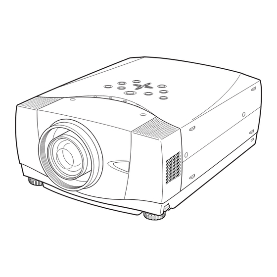
PLC-XP50
:
Note
Model PLC-XP50L does not provide projection lens.
Any information not contained in this manual will be found in the original model's service manual
SM5110500-00 for models PLC-XP55 and PLC-XP55L.
FILE WITH ORIGINAL SERVICE MANUAL (SM5110500)
PRODUCT CODE
1 122 187 00
(MS3AA)
1 122 187 20
(MS3AM)
1 122 188 00
(PS3AA)
1 122 188 20
(PS3AM)
1 122 188 02
(PS3CA)
1 122 188 22
(PS3CM)
Multimedia Projector
- NOTE -
FILE NO.
Model No. PLC-XP50
PLC-XP50L
U.S.A., Canada,
Europe, Asia, Africa
Original Version
Chassis No. MS3-XP5000
MS3-XP50L00
NOTE: Match the Chassis No. on the unit's
back cover with the Chassis No. in the
Service Manual.
If the Original Version Service
Manual Chassis No. does not match
the
unit's,
additional
Literature is required.You must refer to
"Notices" to the Original Service
Manual prior to servicing the unit.
REFERENCE NO.
Service
SS5110575
Advertisement
Table of Contents

Related Manuals for Sanyo PLC-XP50


Summary of Contents for Sanyo PLC-XP50
- Page 1 FILE NO. SERVICE MANUAL Multimedia Projector Model No. PLC-XP50 PLC-XP50L (SUPPLEMENT) U.S.A., Canada, Europe, Asia, Africa Original Version Chassis No. MS3-XP5000 MS3-XP50L00 PLC-XP50 NOTE: Match the Chassis No. on the unit’s back cover with the Chassis No. in the Service Manual.
-
Page 2: Table Of Contents
■ Contents - NOTE - Any information not contained in this manual will be found in the original model's service manual SM5110500-00 for models PLC-XP55 and PLC-XP55L. MAJOR CHANGES as below: - LCD Panels and LCD driving circuit - Projection Lens - Optical parts ■... -
Page 3: Projection Lens
480i, 480p, 575i, 575p, 720p, 1035i and 1080i Scanning Frequency H-sync. 15 ~ 100kHz, V-sync. 50 ~ 100Hz Projection Lens F 1.8 ~2.1 lens with f=48.4mm ~ 62.8mm motor zoom and focus (PLC-XP50) Throw Distance 4.6’ ~ 47.3’ (1.4m ~ 14.4m) (PLC-XP50) Motorized Lens Shift... -
Page 4: Optical Parts Disassemblies
■ Optical Parts Disassemblies * Following assemblies differ from previous assemblies for chassis No. MR3-XP5500 others are the same; - The optical filters has been added. Polarized Glass-In and Optical Filter-In(WV) removal Remove each hex screw and pull the Polarized Glass-In ass’y upward. Remove a stopper and take the glass off upward. -
Page 5: Optical Adjustments
■ Optical Adjustments * Following adjustment differs from previous adjustment for chassis No. MR3-XP5500 others are the same; - Contrast adjustment Before taking optical adjustments below, remove the Cabinet Top and Main Board following to the “Mechanical Disassemblies” Adjustments require a 2.0mm hex wrench and a slot screwdriver. Note: Do not disconnect connectors K8L, K8X, K8D, K8G and K8E on the main board, because the projector can not turn on due to operate the power failure protection. -
Page 6: Adjustments After Parts Replacement
■ Adjustments after Parts Replacement ● ❍ : Adjustment necessary : Check necessary Disassembly / Replaced Parts LCD/ Polarized glass Main Condenser Relay Power Prism Power Lens Lens Board Board Ass’y Board ❍ ● Condenser lens adjustment ❍ ● Relay lens adjustment Contrast Adjustment ●... -
Page 7: Electrical Adjustments
■ Electrical Adjustments ● Circuit Adjustments CAUTION: The each circuit has been made by the fine adjustment at factory. Do not attempt to adjust the follow- ing adjustments except requiring the readjustments in servicing otherwise it may cause loss of per- formance and product safety. - Page 8 Electrical Adjustments NRS adjustment PC black Level adjustment 1. Receive the 16-step gray scale computer signal with 1. Receive the 16-step gray scale computer signal with Input 1 [RGB(Analog)] mode. Input 1 [RGB(Analog)] mode. 2. Enter the service mode. 2. Enter the service mode. TPNRS TP35G 3.
- Page 9 Electrical Adjustments ⁄0 PC gain adjustment Video A/D reference voltage (bottom side) adjustment 1. Receive the 16-step gray scale computer signal with Input 1 [RGB(Analog)] mode. 1. Receive the 16-step gray scale composite video sig- 2. Enter the service mode. nal with Input 3 [Video] mode.
- Page 10 Electrical Adjustments ⁄4 ⁄6 Video gain adjustment Component Y pedestal adjustment 1. Receive the 16-step gray scale composite video sig- 1. Receive the black 0% component 480i video signal nal with Input 3 [video] mode. with Input 3 [Component] mode. 2.
- Page 11 Electrical Adjustments ¤0 ¤4 RGB G pedestal adjustment Common center adjustment 1. Receive the black 0% RGB 480p video signal with 1. Receive the 16-step gray scale computer signal with Input 2 [RGB] mode. Input 1 [RGB(Analog)] mode. 2. Enter the service mode. 2.
-
Page 12: Service Adjustment Data Table
Electrical Adjustments ● Service Adjustment Data Table These initial values are the reference data written from the CPU ROM to memory IC when replaced new memory IC. The adjust- ment items indicated with “✻” are required to readjust following to the “Electrical adjustments”. Other items should be used with the initial data value. - Page 13 Electrical Adjustments Adjustment Item Initial Value Range Input source / Description HS_MASK 0 / 0 / 0 / 0 / 0 or 1 RGB-480i,575i / 480p,575p / 720p,1080i / 1035i 0 / 0 / 0 / 0 YCbCr-480i,575i / 480p,575p / 720p,1080i / 1035i MACRO 1 / 1 / 0 / 0 or 1...
- Page 14 Electrical Adjustments Adjustment Item Initial Value Range Input source / Description ✻ G_V1 0 ~ 255 DAC2 Video center adjustment [G] ✻ B_V1 0 ~ 255 DAC2 Video center adjustment [B] ✻ R_V1 0 ~ 255 DAC2 Video center adjustment [R] ✻...
- Page 15 Electrical Adjustments Adjustment Item Initial Value Range Input source / Description Temp Fan-Out Range High 1350 / 1000 Control range of Fan control voltage by Temperature Sensor A Temp Fan-Out Range Low 780 / 700 / 1000 Diff (UP)Src Range High Difference of temperature between temp-A and temp-C for Fan additional voltage (upward) Diff (UP)Src Range Low Diff(DWN)Src Range High...
- Page 16 Electrical Adjustments Adjustment Item Initial Value Range Input source / Description SYNC_OUT_DELAY_H, 0 ~ 2047 017 / 018 Read only SYNC_OUT_DELAY_V, 0 ~ 2047 019 / 020 Read only IMAGE_OUT_START_H, Set 0 021 / 022 IMAGE_OUT_END_H, 2047 Set 2047 023 / 024 IMAGE_OUT_START_V, 0/ 0/ 0/ 0/ 0/ 0/ 0/ 0/ 0 0 ~ 2047...
- Page 17 Electrical Adjustments Adjustment Item Initial Value Range Input source / Description MOTION_WEIGHT_6, 3/ 3/ 3/ 3/ 3/ 3/ 3/ 3 0 ~ 15 MOTION_WEIGHT_7, 2/ 2/ 2/ 2/ 2/ 2/ 2/ 2 0 ~ 15 MOTION_WEIGHT_8, 1/ 1/ 1/ 1/ 1/ 1/ 1/ 1 0 ~ 15 MOTION_SUM_0, 20/ 20/ 0/ 0/ 20/ 20/ 0/ 0...
- Page 18 Electrical Adjustments Adjustment Item Initial Value Range Input source / Description CR2B_STD 0 / 0 / 0 0 ~ 1023 181 / 182 CB2R_STD 0 / 0 / 0 0 ~ 1023 183 / 184 CR2R_STD 359 / 359 / 359 0 ~ 1023 185 / 186 CB2G_STD...
- Page 19 Electrical Adjustments Adjustment Item Initial Value Range Input source / Description SAM3_AB_ON_ud 0 ~ 3 SAM3_EGE_ud 0 ~ 3 SAM3_Enh_Hset_PC_X_ud 0 ~ 255 SAM3_Enh_Hrst_PC_X_ud 0 ~ 255 SAM3_Enh_Vset_PC_X_ud 0 ~ 255 SAM3_Enh_Vrst_PC_X_ud 0 ~ 255 SAM3_Enh_Hset_PC_F_ud 0 ~ 255 SAM3_Enh_Hrst_PC_F_ud 0 ~ 255 SAM3_Enh_Vset_PC_F_ud 0 ~ 255...
- Page 20 Electrical Adjustments Adjustment Item Initial Value Range Input source / Description SAM3_Cont_Vblk_AV_F_ud 0 ~ 63 SAM3_Cont_Vst_AV/F/V_ud 0 ~ 4095 SAM3_Cont_Vblk/AV/F/V_ud 0 ~ 63 SAM3_Cont_Vst_AV/F/V_ud 0 ~ 4095 SAM3_Cont_Vblk/AV/F/V_ud 0 ~ 63 SAM3_Cont_Hst_AV_Z_ud 0 ~ 4095 SAM3_Cont_Vst_AV_Z_ud 0 ~ 4095 SAM3_Cont_Hblk_AV_Z_ud 0 ~ 63 SAM3_Cont_Vblk_AV_Z_ud 0 ~ 63...
- Page 21 Electrical Adjustments Adjustment Item Initial Value Range Input source / Description DIMMER_CTRL_LEVEL10 0 ~ 32767 DIMMER_CTRL_LEVEL11 0 ~ 32767 DIMMER_CTRL_LEVEL12 0 ~ 32767 DIMMER_CTRL_LEVEL13 0 ~ 32767 DIMMER_CTRL_LEVEL14 1050 0 ~ 32767 DIMMER_CTRL_LEVEL15 1125 0 ~ 32767 DIMMER_AVERAGE_POINT 1 ~ 16 DIMMER_AVERAGE_DATA Read only DIMMER_COLOR_DATA...
- Page 22 Electrical Adjustments Adjustment Item Initial Value Range Input source / Description PAL H BACK PORCH 0 ~ 2048 PAL V BACK PORCH 0 ~ 2048 PAL DISP LINE 0 ~ 2048 PAL CLAMP 0 ~ 2048 Group: 512 HDTV 1080i-60 Gakaku TOTAL DOTS 1206 0 ~ 2048...
- Page 23 Electrical Adjustments Adjustment Item Initial Value Range Input source / Description DISP LINE 1050 0 ~ 2048 CLAMP 0 ~ 2048 Group: 522 RGB 1035i Gakaku TOTAL DOTS 1206 0 ~ 2048 DISP DOTS 1024 0 ~ 2048 RGB 1035i H BACK PORCTH 0 ~ 2048 V BACK PORCTH...
-
Page 24: Test Points And Locations
Electrical Adjustments Test Points and Locations ● MAIN BOARD TP1301E TP1312 TP1311 TPFN4 TPFN4 TE801 TP801 IC801 TP9851 TP9852 TP351 TP9885 TP9884 TP18V IC808 TPV1R TPV2R TPSH_R_S IC807 TPT2 IC2501 TPT0 TPT3 TP306 K35R TE301 TPSDATA3 TP308 TPIRMSTB TE9401 TPSCLK3 TP307 TPV1G TPV1G... -
Page 25: Chassis Block Diagrams
■ Chassis Block Diagrams ● Chassis over view MOTORS B-LCD PANEL G-LCD PANEL R-LCD PANEL IC351 FLASH IC4503 IC341 SRAM IC4531 YUV SW Y,Cb,Cr IC1141 NT/PAL-SW IC1631,IC1632 IC5304 AUDIO-AMP. IC1141 SYNC SEP. NT/PAL-SW IC201 IC5302 RGB-SW SYNC SW IC4104 IC1652 IC5301 IC1201 CSYNC SW... - Page 26 Chassis Block Diagrams ● Video signal processing stage IC301 SCAN CONVERTER IC3211 IC3212 IC3213 IC4251 IC4261 IC4271 BUFFER BUFFER BUFFER BUFFER BUFFER BUFFER IC8001 IC231 IC4201 DVI-RECEIVER IP CONVERTER <AD9888> <SII169> <TC240C4FTB> IC2311 <MB40C348> RGB : L OTHERS : H NOT_RGB IC4503 IC4531...
-
Page 27: Troubleshooting
Chassis Block Diagrams ● LCD panel driving stage SCLK3/SDATA3/STB3 IC9402 SDRAM <EM638325> PW_RXD/TXD TP35B SDIF IC501 B-LCD B-LCD DRIVER DBSH PANEL RD/WRL/WRH/CS <L3E06110> BAOUT GAOUT BAOUT TP35G IC1501 G-LCD G-LCD DRIVER DGSH PANEL <L3E06110> TP308 TP307 TP35R IC2501 R-LCD R-LCD DRIVER DRSH PANEL <L3E06110>... -
Page 28: System Controls
Chassis Block Diagrams ● System Controls 21-24 35-36 31-26 37-38 51-54 41-42 IC9884 IC8091 SERIAL- EEPROM PARALLEL SDA6 SCL6 IC9851 SERIAL- IC9405 PARALLEL IC8081 EEPROM IC9501 CAPTURE SDA3 SCL3 IC212 IC9401 PICTURE IC8001 IC4201 IC4861 RECEIVER BUFFER CONV. IC1801 IC9931 IC7801 I/O EXPANDER EXPANDER... -
Page 29: Power Supply Lines
■ Power Supply Lines ● Power supply & protection circuit FN904 FN906 FN907 FN903 K70C 49-52 9-10 49-52 K30P CN16C K10A 6VPC K70B 15.5V 3.3V S-5V D4815 15VP D4814 9-11 PFC_SW IC_RESET R697,R698 P_FAIL P_FAIL FAN_DRIVE FAN_CONT1 FAN_CONT1 FAN_CONT2 FAN_CONT2 IC807 PRESSURE IC9851... -
Page 30: Control Port Functions
■ Control Port Functions ❈ Differences as below: ● System Control & I/O Port Table (IC801) See original page.52-53 Pin No. Name Function Name Function Polarity PE6/TIOC2A Original Not used Supplement 3.3VL_SW 3.3VL_On/Off ON = H PF7/AN7 Original OPT3 Not used Supplement OPT3 Panel Option... -
Page 31: Waveforms
■ Waveforms VIDEO-IN <IC3101-1> Y-IN <IC3101-5> C-IN <IC3101-7> H-SYNC-OUT <IC3101-9> V-SYNC-OUT <IC3101-4> Sandcastle-OUT <IC3101-10> Y-IN <TP13GY> CB-IN <TP13BCB> CR-IN <TP13RCR> R <TP21R> G <TP21G> B <TP21B> R-S&H OUT <TP35R> G-S&H OUT <TP35G> B-S&H OUT <TP35B> -31-... -
Page 32: Ic Block Diagrams
■ IC Block Diagrams ❈ Additional items as below: See original page.59-70 ● L3E07070 <Signal Processor for TFT LCD, IC401> ● L3E06110 <LCD Driver, > IC501, IC1501, IC2501 CONTROL LOGIC DAC LATCHES -32-... -
Page 33: Service Parts Lists
■ Electrical Parts List MS3-XP5000, MS3-XP50L00 Product safety should be considered when a component replacement is made in any area of a projector. Components indicated by a mark in this parts list and the circuit diagram show components whose value have special significance to product safety. - Page 34 MS3-XP5000, MS3-XP50L00 Electrical Parts List Note: Parts order must contain Chassis No., Part No., and Descriptions. ● OUT OF CIRCUIT BOARD RC Front Board Sensor1 Board FN901 Intake Fan FN904 Cooling Fan Drive Board Power Board Sub Power Main Board Board Lamp Ballast FN902...
- Page 35 MS3-XP5000, MS3-XP50L00 Electrical Parts List Key No. Part No. Description Key No. Part No. Description D6893 407 203 7902 LED SML-210MT T86 M ASSEMBLIED BOARDS D6894 407 203 7803 LED SML-210LT T86 M D6895 407 203 7704 LED SML-210DT T86 L 610 293 1815 ASSY,PWB,CONTROL MA8A MISCELLANEOUS...
- Page 36 MS3-XP5000, MS3-XP50L00 Electrical Parts List Key No. Part No. Description Key No. Part No. Description 405 002 0308 TR 2SA1037K T146 R 405 002 0308 TR 2SA1037K T146 R 405 002 0407 TR 2SA1037K T146 S 405 002 0407 TR 2SA1037K T146 S 405 002 6706 TR 2SA1179-M6-TB 405 002 6706...
- Page 37 MS3-XP5000, MS3-XP50L00 Electrical Parts List Key No. Part No. Description Key No. Part No. Description 405 163 1602 TR 2SC2812N-L6-TB0 Q3302 405 014 4509 TR 2SC2412K T146 R 405 163 1701 TR 2SC2812N-L7-TB0 405 014 4608 TR 2SC2412K T146 S Q2101 405 014 4509 TR 2SC2412K T146 R...
- Page 38 MS3-XP5000, MS3-XP50L00 Electrical Parts List Key No. Part No. Description Key No. Part No. Description 405 014 4608 TR 2SC2412K T146 S 405 002 6904 TR 2SA1179-M7-TB 405 015 8704 TR 2SC2812-L6-TB 405 163 1503 TR 2SA1179N-M6-TB 405 015 8902 TR 2SC2812-L7-TB 405 163 2708 TR 2SA1179N-M7-TB...
- Page 39 MS3-XP5000, MS3-XP50L00 Electrical Parts List Key No. Part No. Description Key No. Part No. Description 405 015 8902 TR 2SC2812-L7-TB IC3212 410 321 8300 IC TC74VCX16244FT 405 163 1602 TR 2SC2812N-L6-TB0 IC3213 410 321 8300 IC TC74VCX16244FT 405 163 1701 TR 2SC2812N-L7-TB0 IC3214 410 362 6501...
- Page 40 MS3-XP5000, MS3-XP50L00 Electrical Parts List Key No. Part No. Description Key No. Part No. Description IC8081 409 487 5803 IC 24C01CT/SN C1351 403 304 1801 ELECT 100U M 6.3V IC8091 409 558 7200 IC 24C02CT-I/SN 403 373 7704 ELECT 100U M 6.3V IC8092 409 434 8109...
- Page 41 MS3-XP5000, MS3-XP50L00 Electrical Parts List Key No. Part No. Description Key No. Part No. Description C209 403 164 0204 CERAMIC 0.1U Z C2357 403 304 1801 ELECT 100U M 6.3V C210 403 322 7809 ELECT 220U M 6.3V 403 373 7704 ELECT 100U M 6.3V...
- Page 42 MS3-XP5000, MS3-XP50L00 Electrical Parts List Key No. Part No. Description Key No. Part No. Description C273 403 338 0108 CERAMIC 0.039U K C3154 403 283 6309 CERAMIC 1U Z C274 403 283 6309 CERAMIC 1U Z C3156 403 164 0204 CERAMIC 0.1U Z C276...
- Page 43 MS3-XP5000, MS3-XP50L00 Electrical Parts List Key No. Part No. Description Key No. Part No. Description C3538 403 164 0204 CERAMIC 0.1U Z C4230 403 164 0204 CERAMIC 0.1U Z C3558 403 164 0204 CERAMIC 0.1U Z C4231 403 304 2105 ELECT 47U M 6.3V...
- Page 44 MS3-XP5000, MS3-XP50L00 Electrical Parts List Key No. Part No. Description Key No. Part No. Description C4821 403 164 0204 CERAMIC 0.1U Z C6312 403 164 0204 CERAMIC 0.1U Z C4822 403 164 0204 CERAMIC 0.1U Z C6313 403 113 3805 CERAMIC 1000P K C483...
- Page 45 MS3-XP5000, MS3-XP50L00 Electrical Parts List Key No. Part No. Description Key No. Part No. Description C8007 403 304 1801 ELECT 100U M 6.3V C9407 403 164 0204 CERAMIC 0.1U Z 403 373 7704 ELECT 100U M 6.3V C9411 403 164 0204 CERAMIC 0.1U Z C8008...
- Page 46 MS3-XP5000, MS3-XP50L00 Electrical Parts List Key No. Part No. Description Key No. Part No. Description 403 325 3303 CERAMIC 0.1U K 645 028 5981 R-NETWORK 10X4 1/16W C9885 403 155 1609 CERAMIC 33P J RB801 645 037 4920 R-NETWORK 3.3KX4 0.063W C9886 403 155 1609 CERAMIC...
- Page 47 MS3-XP5000, MS3-XP50L00 Electrical Parts List Key No. Part No. Description Key No. Part No. Description R1160 401 105 0603 MT-GLAZE 10K JA 1/16W R1518 401 105 0405 MT-GLAZE 100 JA 1/16W R1162 401 105 0504 MT-GLAZE 1K JA 1/16W R1519 401 105 0405 MT-GLAZE 100 JA 1/16W...
- Page 48 MS3-XP5000, MS3-XP50L00 Electrical Parts List Key No. Part No. Description Key No. Part No. Description R1843 401 105 0603 MT-GLAZE 10K JA 1/16W R2342 401 217 4100 MT-GLAZE 22K FA 1/16W R1852 401 105 0603 MT-GLAZE 10K JA 1/16W R2344 401 217 4100 MT-GLAZE 22K FA 1/16W...
- Page 49 MS3-XP5000, MS3-XP50L00 Electrical Parts List Key No. Part No. Description Key No. Part No. Description R271 401 105 7909 MT-GLAZE 0.000 ZA 1/16W R3176 401 105 0504 MT-GLAZE 1K JA 1/16W R272 401 105 0405 MT-GLAZE 100 JA 1/16W R3177 401 105 0504 MT-GLAZE 1K JA 1/16W...
- Page 50 MS3-XP5000, MS3-XP50L00 Electrical Parts List Key No. Part No. Description Key No. Part No. Description R3582 401 105 0405 MT-GLAZE 100 JA 1/16W R4283 401 105 7909 MT-GLAZE 0.000 ZA 1/16W R359 401 105 7909 MT-GLAZE 0.000 ZA 1/16W R4284 401 105 7909 MT-GLAZE 0.000 ZA 1/16W...
- Page 51 MS3-XP5000, MS3-XP50L00 Electrical Parts List Key No. Part No. Description Key No. Part No. Description R4604 401 105 7909 MT-GLAZE 0.000 ZA 1/16W R533 401 105 7909 MT-GLAZE 0.000 ZA 1/16W R4605 401 105 7909 MT-GLAZE 0.000 ZA 1/16W R534 401 105 7909 MT-GLAZE 0.000 ZA 1/16W...
- Page 52 MS3-XP5000, MS3-XP50L00 Electrical Parts List Key No. Part No. Description Key No. Part No. Description R6318 401 105 7909 MT-GLAZE 0.000 ZA 1/16W R8019 401 113 6406 MT-GLAZE 5.1K JA 1/16W R6319 401 105 7909 MT-GLAZE 0.000 ZA 1/16W R802 401 105 5301 MT-GLAZE 4.7K JA 1/16W...
- Page 53 MS3-XP5000, MS3-XP50L00 Electrical Parts List Key No. Part No. Description Key No. Part No. Description R851 401 105 7909 MT-GLAZE 0.000 ZA 1/16W R9451 401 105 0306 MT-GLAZE 10 JA 1/16W R8511 401 105 2904 MT-GLAZE 22K JA 1/16W R9452 401 105 7909 MT-GLAZE 0.000 ZA 1/16W...
- Page 54 MS3-XP5000, MS3-XP50L00 Electrical Parts List Key No. Part No. Description Key No. Part No. Description R9864 401 105 7909 MT-GLAZE 0.000 ZA 1/16W L4501 645 026 0964 INDUCTOR,10U K R9866 401 105 8005 MT-GLAZE 1M JA 1/16W L4541 645 050 8448 IMPEDANCE,1000 OHM P R9867 401 105 0405...
- Page 55 MS3-XP5000, MS3-XP50L00 Electrical Parts List Key No. Part No. Description Key No. Part No. Description D4819 407 149 0807 DIODE 1SS355-TE-17 C628 403 157 3304 CERAMIC 68P J C629 403 157 6602 CERAMIC 470P K D5521 407 071 0104 ZENER DIODE DZD12Y-TA C631 403 298 9609 CERAMIC...
- Page 56 MS3-XP5000, MS3-XP50L00 Electrical Parts List Key No. Part No. Description Key No. Part No. Description R651 401 237 0007 MT-GLAZE 47K JA !PC601 407 223 7302 PC TLP421F(D4-GB-TP4) R652 401 237 0007 MT-GLAZE 47K JA 407 223 8309 PC TLP421F(D4-GR-TP4) R653 401 237 0007 MT-GLAZE...
- Page 57 MS3-XP5000, MS3-XP50L00 Electrical Parts List Key No. Part No. Description Key No. Part No. Description C6632 403 325 8506 ELECT 1000U M R6647 401 105 4007 MT-GLAZE 330 JA 1/16W C6633 403 334 6906 ELECT 1000U M 6.3V R6648 401 230 4705 MT-GLAZE 680 JA C6634...
- Page 58 MS3-XP5000, MS3-XP50L00 Electrical Parts List Key No. Part No. Description Key No. Part No. Description R6781 401 105 0603 MT-GLAZE 10K JA 1/16W C1631TM 403 325 8605 ELECT 220U M R6782 401 105 5301 MT-GLAZE 4.7K JA 1/16W C1632 403 323 8805 CERAMIC 2.2U Z R6783...
- Page 59 MS3-XP5000, MS3-XP50L00 Electrical Parts List Key No. Part No. Description Key No. Part No. Description 405 163 1602 TR 2SC2812N-L6-TB0 CAPACITOR !C601 404 081 4702 MT-POLYEST 0.22U M 275V 405 163 1701 TR 2SC2812N-L7-TB0 !C602 Q1204 405 014 4509 TR 2SC2412K T146 R 404 081 4702 MT-POLYEST 0.22U M...
- Page 60 MS3-XP5000, MS3-XP50L00 Electrical Parts List Key No. Part No. Description Key No. Part No. Description 405 015 8704 TR 2SC2812-L6-TB 405 015 8704 TR 2SC2812-L6-TB 405 015 8902 TR 2SC2812-L7-TB 405 015 8902 TR 2SC2812-L7-TB 405 163 1602 TR 2SC2812N-L6-TB0 405 163 1602 TR 2SC2812N-L6-TB0 405 163 1701...
- Page 61 MS3-XP5000, MS3-XP50L00 Electrical Parts List Key No. Part No. Description Key No. Part No. Description C1234 403 164 0204 CERAMIC 0.1U Z C4164 403 321 2607 ELECT 10U M C1236 403 164 0204 CERAMIC 0.1U Z C4166 403 164 0204 CERAMIC 0.1U Z C2004...
- Page 62 MS3-XP5000, MS3-XP50L00 Electrical Parts List Key No. Part No. Description Key No. Part No. Description R1037 401 105 2805 MT-GLAZE 2.2K JA 1/16W R2007 401 105 7909 MT-GLAZE 0.000 ZA 1/16W R1038 401 105 2706 MT-GLAZE 220 JA 1/16W R2008 401 105 7909 MT-GLAZE 0.000 ZA 1/16W...
- Page 63 MS3-XP5000, MS3-XP50L00 Electrical Parts List Key No. Part No. Description Key No. Part No. Description R3862 401 105 2805 MT-GLAZE 2.2K JA 1/16W R5006 401 035 4108 MT-GLAZE 0.000 ZA 1/8W R3863 401 105 7909 MT-GLAZE 0.000 ZA 1/16W R5007 401 105 2003 MT-GLAZE 1.8K JA 1/16W...
- Page 64 MS3-XP5000, MS3-XP50L00 Electrical Parts List Key No. Part No. Description Key No. Part No. Description L1007 645 044 8850 FILTER,EMI 400MHZ D5311 407 224 6502 ZD UDZS4.7B-TE-17 L1008 645 044 8843 FILTER,EMI 200MHZ D5312 407 224 6502 ZD UDZS4.7B-TE-17 L1009 645 044 8843 FILTER,EMI 200MHZ D7308...
- Page 65 MS3-XP5000, MS3-XP50L00 Electrical Parts List Key No. Part No. Description Key No. Part No. Description R7003 401 105 0405 MT-GLAZE 100 JA 1/16W ACCESSORIES R7004 401 105 0405 MT-GLAZE 100 JA 1/16W R7006 401 113 4907 MT-GLAZE 200 JA 1/16W R7007 401 105 2409 MT-GLAZE...
-
Page 66: Mechanical Parts List
■ Mechanical Parts List MS3-XP5000, MS3-XP50L00 Note: Parts order must contain Chassis No., Part No., and Descriptions. ● CABINET PARTS -66-... - Page 67 CABINET FRONT SERVICE-MA8 (Including Key No.24-a) (Including Key No. 5, 6) 24-a 610 306 5922 ASSY,PWB,BASE NET MR3A 645 048 6043 BADGE,SANYO*35.0X7.5L35.0 610 303 8773 ASSY,PANEL NET A-MA8AA 610 289 1812 BADGE V MARK S-MK6A 610 303 8780 ASSY,PANEL NET B-MA8AA...
-
Page 68: Optical Parts List
Note : No. of PLC-XP50L This item belongs to "Accessories". This item belongs to "Accessories". No.70 includes No.24 and No.45. Note : No.71 of PLC-XP50 Note : No.73 of PLC-XP50L (PLC-XP50L does not This item belongs to "Accessories". provide the projection lens.) Refer to "Lens instruction manual". - Page 69 MS3-XP5000, MS3-XP50L00 Optical Parts List Note: Parts order must contain Chassis No., Part No., and Descriptions. 64: Red Part No. Polarized Grass 65: Green 5 * * Film side Optical Filter 63: Red & Green Part No. Polarized Grass 66: Blue 5 * * Film side -69-...
- Page 70 MS3-XP5000, MS3-XP50L00 Optical Parts List 72-d: Red 72-e: Green 72-f: Blue 72-g: Green & Blue (Red no use) 72-a: Red 72-b: Green 72-c: Blue -70-...
- Page 71 MS3-XP5000, MS3-XP50L00 Optical Parts List CAUTION: Part must be placed in specified direction when replacing the optical parts. Please see “Optical Parts Disassemblies” for further instructions. -71-...
- Page 72 SANYO Electric Co., Ltd. (MS3AA) DEC. 2003 BB 400 Printed in Japan...
- Page 73 PLC-XP50L MS3-XP50L00 These schematic diagrams and printed wiring board drawings are part of the serv- ice manual original for chassis No. MS3-XP5000/XP50L00 models PLC-XP50/50L. File with the service manual No. SS5110575-00. Note: All the information of part numbers and values indicated on these diagrams are at the beginning of production.
-
Page 74: Parts Description And Reading In Schematic Diagram
■ Parts description and reading in schematic diagram MS3-XP5000, MS3-XP50L00 1. The parts specification of resistors, capacitors and Resistor Reading coils are expressed in designated code. Please check Example 1/2 D J 10K B the parts description by the following code table. 2. -
Page 75: Schematic Diagrams
■ Schematic Diagrams K911P K911S L6611 K66G J11MC J11MB DRIVE K16N 020N J10EG 020N L2E6470KN L6612 R6642 090G J10EP L2M9470KN 1/16GF C6701 SOUND R-OUT R6654 D6626 R6647 R6621 R6623 S-5V 040G SP901 POWER FACTOR CORRECTION C6752 C6762 D6602 6.8KC R6624 25KZ A10B R6645... - Page 76 INPUT-1 RGB DIGITAL INPUT IC1201 AD8185ARU R1201 L1001 C1207 R1208 IN1_R 1/16GJ100C R3006 F34EA407G 1/16GJ10KC Q1201 25KZ0.1GQF R1217 K10F 1/16GJ2.2KC IN0A 1/16GJ10KC C1201 J11B4930N R1211 SC1001 SYNC_OFF R1001 C3003 Z30B0120G 1/3GJ75 DGND 25KZ0.1GQF R3007 K30P R1202 C1208 R1209 1/16GZ0C R1016 1/16GJ100C R3009 J11MD540G...
- Page 77 C3154 R3171 Q3161 10KZ1UGQFZ 1/16GJ K10C 3.3KC CG_RIN CG_R CVBS R3174 R3164 1/16GJ 1/16GJ CVBS R4651 3.3KC 1/16GJ Q3162 R3172 1/16GJ Q4651 3.3KC R4652 2SA1037 CG_G CG_GIN R3176 1/16GJ1KC R3163 1/16GJ C4651 1/16GJ 3.3KC IC3102 Q3163 R3173 R4682 R4686 C4652 BA05FP-E2 D3102 1/16GJ...
- Page 78 D8061 RB051L 5VDVI2 -40G 5VDVI RB8011 D8062 R1EA1004G RB8014 RB051L ;R1A41004G RB8009 IC8092 -40G R1EA1004G R1EA1004G ;R1A41004G See Parts List ;R1A41004G C8062 D_BO7 25KZ0.1GQFZ D8064 HDCP_CLK 1SS355 D_BO6 C8061 3.3V_DVI_PF D_BO5 6.3EM47WM PC_CLK DDC_CLK D_BO4 3.3V_DVI D_BO3 L8001 SCL6 HD_DDC_DATA D_BO2 L2PD2R2MG C8001...
- Page 79 D6301 1SS355 3.3V_PF 3.3V TE4202 C_DQ[0-31] L4232 J30A00102 L2A7100KG C6314 C6313 C6311 C6309 L6301 R6316 25KZ KK1000 KK1000 25KZ L3DE102PG 1/16GZ0C 0.1GQFZ GQBZ GQBZ 0.1GQFZ RCRO_B[0-7] 3.3V R6301 1/16GZ0C C4251 C_AD[9] C_DQ[0-63] 6.3EM100WM R4262 ;6.3EM100F1 C4202 6.3EM100WM C4203 GCLK_PW R4277 R4264 ;6.3EM100F1 25KZ0.1...
- Page 80 D[0-15] Not used TP1301E J30A00102 R391 S3.3V S3.3V_S2.5V S3.3V IC392 D[8] D[0] D391 D392 SI-3025LSA-TL 1SS355 D[9] D[1] C394 1SS355 C392 11 12 6.3EM100WM 6.3EM100WM D[2] 13 14 ;6.3EM100F1 ;6.3EM100F1 D[3] D[10] S2.5V D[0-15] 15 16 IC3211 IC3212 IC3213 D[11] L3211 C395 17 18...
- Page 81 TPV2B TPV2B NTV2B J30A00102 B_V2 FROM 3.3V IC4501(DAC) TPV1B TPV1B R555 R556 NTV1B J30A00102 BAOUT[0-9] B_V1 1/16GJ10KC 1/16GJ5.1KC GAOUT[0-9] REF_B C9465 R9467 25KZ 1/16GJ RAOUT[0-9] R557 330C BLUE GQFZ R9462 1/16GJ12KC R548 R543 1/16 1/16 R3505 SD_CLK R549 GZ0C R9468 R9469 GZ0C 1/16GJ2.2C...
- Page 82 LENS SHIFT DRIVE LAMP CONNECT POWER CONTROL SENSOR "K16R" "K30P" "K30Q" "K30R" "K9C" BALLAST "K66F" POWER POWER POWER "K68A" "K28A" "K16I" "K7B" "K66E" "K66D" "K66V" J10EP J10EG (TO THRMO_SENS) 130G 110G K10Q K10R J10EG090G K10P J10ML J10ML J10EP J10EP J10ML 540G 540G J10EG090G...
-
Page 83: Printed Wiring Board Diagrams
■ Printed Wiring Board Diagrams CAUTION This projector is isolated from AC line by using the internal converter transformer. Please pay attention to the following notes in servicing 1. Do not touch the part on hot side (primary circuit) or both parts on hot and cold FILTER (SIDE:A) FILTER (SIDE:B) sides (secondary circuit) at the same time. - Page 84 MAIN (SIDE:A) LENS SHIFT CONNECT CONTROL “K68A” RC “K28A” SUB POWER “K66E” SUB POWER “K66D” “K9C” R1859 R1862 TP35B FN904 R-LCD PANEL C7832 Q1852 C4805 IC501 C7833 B-LCD PANEL R4896 D3561 D4803 C507 D4811 TP35R C3564 R514 RB2501 RB2502 RB2503 C504 TPSH_B_S D4891...
- Page 85 MAIN (SIDE:B) LAMP BALLAST “K7B” SUB POWER “K66F” SENSOR1 “K16I” R4867 R4863 R4841 RB504 D4813 C4808 C511 DRIVE “K16R” R4868 C526 R4869 C525 R506 R502 C524 R504 C4811 R2001 D4812 C502 C523 RB9802 R4840 D4815 RB9806 R2000 R512 C522 R4846 C501 R9804 C521...
- Page 86 POWER (SIDE:A) DRIVE (SIDE:A) DRIVE “CN16C” LAMP BALLAST “K7A” FILTER “K6AB” SPEAKERS MAIN K6AC (LIVE HEATSINK) “K10T” “K8T” CN6C CAUTION: C609 C608 SHOCK HAZARD. PTH601 TEST BEFORE TOUCHING L681 K16N K16S K16U K16R DS601 DB601 DS602 R1672 ZOOM/ R699 FB601 C692 C607 C691...
- Page 87 SUB POWER (SIDE:A) SUB POWER (SIDE:B) POWER FN901 FN905 A/V “K10U” “CN6A” FN902 MAIN “K8C” K66H K66G K66M K66L K66S R6732 D6610 D6728 R6655 C6709 R6731 C6662 D6616 R6730 R6721 D6614 R6650 R6642 R6725 MAIN “K8V” C6613 C6667 C6662 C6619 C6659 C6761 R6640...
- Page 88 AV (SIDE:A) AV (SIDE:B) MAIN “K10B” “K10A” “K10C” K30Q K30P K30R C1002 R1064 R1041 R1038 Q1002 R1066 R1011 R1006 1AA4B10C39500 Q1004 C1004 D3002 R1067 PARTS SIDE R5356 L3002 SC1002 R1238 D5311 D3001 Q1003 R5377 K20H C5313 R1239 C3002 R5318 Q1202 Q1203 R3001 SC1001...
- Page 89 ■ Pin description of diode, transistor and IC MS3-XP5000, MS3-XP50L00 ● Diode ● Diode K: Cathode A: Anode ● Transistor/FET ● Transistor/FET C: Collector D: Drain B: Base G: Gate Index E: Emitter S: Source C1 C2 C1 C2 ● IC ●...
- Page 90 Diagrams & Drawings PLC-XP50,PLC-XP50L...
Need help?
Do you have a question about the PLC-XP50 and is the answer not in the manual?
Questions and answers