Table of Contents
Advertisement
Quick Links
Advertisement
Table of Contents

Related Manuals for Black Box ServSwitch Wizard SW651A


Summary of Contents for Black Box ServSwitch Wizard SW651A
- Page 1 MARCH 2001 SW651A SW652A...
- Page 2 We apologize for the omission. © Copyright 2001. Black Box Corporation. All rights reserved. BLACK BOX and the logo are registered trademarks, and ServSwitch and ServSwitch Wizard are trademarks, of Black Box Corporation. PC/AT is a registered trademark of International Business Machines Corporation. CUSTOMER Order toll-free in the U.S.: Call 877-877-BBOX (outside U.S.
- Page 3 ServSwitch system that’s just right for you. The ServSwitch ™ family from Black Box—the one-stop answer for all your KVM- switching needs! This manual will tell you all about your new ServSwitch™ Wizard, including how to install, operate, and troubleshoot it. For an introduction to the ServSwitch Wizard, see Chapter 2.
- Page 4 TRADEMARKS USED IN THIS MANUAL BLACK BOX and the logo are registered trademarks, and ServSwitch and ServSwitch Wizard are trademarks, of Black Box Corporation. Apple and Macintosh are registered trademarks of Apple Computer, Inc. Compaq and Alpha are registered trademarks of Compaq Computer Corporation.
- Page 5 FCC/IC STATEMENTS FEDERAL COMMUNICATIONS COMMISSION AND INDUSTRY CANADA RADIO-FREQUENCY INTERFERENCE STATEMENTS This equipment generates, uses, and can radiate radio-frequency energy, and if not installed and used properly, that is, in strict accordance with the manufacturer’s instructions, may cause interference to radio communication. It has been tested and found to comply with the limits for a Class A computing device in accordance with the specifications in Subpart J of Part 15 of FCC rules, which are designed to provide reasonable protection against such interference when the equipment is...
- Page 6 SERVSWITCH™ WIZARD EUROPEAN UNION DECLARATION OF CONFORMITY This equipment has been tested and found to comply with the limits for a class B computing device in accordance with the specifications in the European standard EN55022. These limits are designed to provide reasonable protection against harmful interference.
- Page 7 NOM STATEMENT NORMAS OFICIALES MEXICANAS (NOM) ELECTRICAL SAFETY STATEMENT INSTRUCCIONES DE SEGURIDAD 1. Todas las instrucciones de seguridad y operación deberán ser leídas antes de que el aparato eléctrico sea operado. 2. Las instrucciones de seguridad y operación deberán ser guardadas para referencia futura.
- Page 8 SERVSWITCH™ WIZARD 12. Precaución debe ser tomada de tal manera que la tierra fisica y la polarización del equipo no sea eliminada. 13. Los cables de la fuente de poder deben ser guiados de tal manera que no sean pisados ni pellizcados por objetos colocados sobre o contra ellos, poniendo particular atención a los contactos y receptáculos donde salen del aparato.
-
Page 9: Table Of Contents
TABLE OF CONTENTS Contents Chapter Page 1. Specifications ..................... 9 2. Introduction ..................... 11 2.1 Features and Benefits ............... 11 2.2 The Complete Package ..............12 2.3 The ServSwitch Wizard Illustrated ........... 13 2.4 Safety Concerns ................. 14 3. Installation ....................15 3.1 What You Will Need ................ - Page 10 5.13 Upgrading the Wizard’s Firmware ..........48 6. Troubleshooting ..................50 6.1 Things to Try ..................50 6.2 Calling Black Box ................52 6.3 Shipping and Packaging ..............52 Appendix: Cable Guidelines ................53 A.1 Cabling from the Keyboard, Monitor, and Mouse to the ServSwitch Wizard .................
-
Page 11: Specifications
CHAPTER 1: Specifications 1. Specifications Compliance — CE (EN55022 Class B); FCC Part 15 Subpart J Class A, IC Class/classe A Standards — VGA, SVGA, XGA, XGA-2, SXGA, or UXGA video; supports VESA DDC, DDC1, and DDC2 signaling Interfaces — Video: VGA;... - Page 12 SERVSWITCH™ WIZARD All rear-mounted: Connectors — User port: (1) HD15 female for monitor attachment, (2) 6-pin mini-DIN female for keyboard and mouse attachment; CPU ports ([2] on SW651A, [4] on SW652A): (1) HD15 female for video-port attachment, (2) 6-pin mini-DIN female for keyboard- and mouse- port attachment;...
-
Page 13: Introduction
CHAPTER 2: Introduction 2. Introduction The ServSwitch™ Wizard is a high-performance keyboard-, monitor-, and mouse- sharing device that supports a wide range of IBM ® PC compatible hardware and software platforms, including some high-end IBM PS/2 ® compatible computers (IBM RS/6000 ®... -
Page 14: The Complete Package
SERVSWITCH™ WIZARD • Mixed PC/AT and PS/2 keyboards and PS/2 and RS-232 mice supported as ® standard. • Supports keyboard modes 1, 2, and 3, as well as both “prompt” and “stream” mouse modes, for maximum compatibility. • Support for Microsoft ®... -
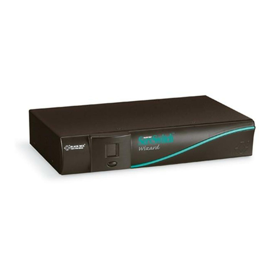
Page 15: The Servswitch Wizard Illustrated
CHAPTER 2: Introduction 2.3 The ServSwitch Wizard Illustrated Button for Display shows changing status and channels and mouse/keyboard entering data activity configuration mode Figure 2-1. The ServSwitch Wizard’s front panel. Connector Expansion port for Remote-Control Module, optional RS-232 control, multi- CPU ports 1 through 4 (ports 3 and 4 Control Control-port... -
Page 16: Safety Concerns
SERVSWITCH™ WIZARD 2.4 Safety Concerns As you prepare to install the ServSwitch Wizard, please keep these things in mind: • The Wizard is for use in dry, oil-free indoor environments only. • Do not attempt to fix the Wizard yourself. •... -
Page 17: Installation
CHAPTER 3: Installation 3. Installation 3.1 What You Will Need You’ll need these things to be in place before you can install your ServSwitch Wizard: • Cables to connect the ServSwitch Wizard to the keyboard, video, and mouse ports of each of your computers. If you’ll be installing synchronized or cascaded Wizards, you’ll also need cables to attach the Wizards to each other. -
Page 18: Placement
SERVSWITCH™ WIZARD 3.2 Placement The ServSwitch Wizard should be placed on a desktop or shelf near your monitor and peripherals. You can use the optional Remote-Control Module if you want to put a Wizard farther from your monitor and peripherals. 3.3 Connecting Your Equipment NOTES When you connect devices to Wizards’... -
Page 19: Systems With A Single Wizard
CHAPTER 3: Installation 3.3.1 S YSTEMS WITH A INGLE IZARD Make sure that the Wizard is unplugged and powered down. If possible, turn off and unplug all of the devices that you want to attach to it. (If you have to “hot- plug”... -
Page 20: Cascaded Wizard Systems For More Than Four Cpus
SERVSWITCH™ WIZARD 3.3.2 C ASCADED IZARD YSTEMS FOR Multiple ServSwitch Wizards can be cascaded (connected together in a one-to- many scheme) in order to increase the maximum number of available CPU ports in your KVM-switching system. (Note that each Wizard in a cascade must be powered through a power supply and not from the keyboard interface.) This can be particularly useful where clusters of computers are located some distance from each other, because each Wizard acts as a kind of signal booster or repeater and... - Page 21 CHAPTER 3: Installation Finally, connect each computer CPU to the Wizard system by running cabling from the CPU’s keyboard, mouse, and video ports to the matching connectors in one of the CPU ports on one of the subsidiary Wizards. As with the master-to- subsidiary Wizard connections, this cabling can be either separate keyboard-, mouse-, and video-extension cables or ServSwitch Duo CPU-Extension Cable.
-
Page 22: Synchronized Wizard Systems For Cpus With
SERVSWITCH™ WIZARD 3.3.3 S YNCHRONIZED IZARD YSTEMS FOR S WITH ULTIPLE IDEO UTPUTS Some business environments, such as engineering and financial services, often make use of CPUs with multiple video outputs (as in, multiple video cards and/or video cards with multiple video heads). This is because these environments frequently require more “video real estate”... - Page 23 CHAPTER 3: Installation Connect each computer CPU to the synchronized Wizard system. First run cabling from the CPU’s keyboard port, mouse port, and primary video output to the matching connectors in one of the master Wizard’s “CPU ports.” This cabling can be either separate male-to-male keyboard-, mouse-, and video-extension cables, or our three-in-one ServSwitch Duo CPU-Extension Cable.
-
Page 24: Servswitch Duo Cables, Servswitch Extenders, And Pc/At Adapters
With the Fiber Extender, you’ll need a multimode fiberoptic cable with at least five fiber strands to run between the Extender’s Local and Remote Units. Call Black Box Technical Support for help planning an Extender- assisted ServSwitch Wizard system. - Page 25 CHAPTER 3: Installation 6-Pin 6-Pin mini-DIN mini-DIN HD15 10" (25.4 9" (22.9 Cross-section: Central video strand Keyboard and mouse strands molded to sides Figure 3-4. The ServSwitch Duo cables. To connect computers with serial mouse ports and/or PC/AT style keyboard ports, you’ll need adapters like those shown in Figure 3-5.
-
Page 26: Powering The Wizard
SERVSWITCH™ WIZARD 3.4 Powering the Wizard Once you’ve installed your ServSwitch Wizard system and attached your equipment to it, you need to apply power to each Wizard. You can do this in either of two ways: If you are not using the optional power supply: Power up the attached CPUs. The ServSwitch Wizard (which has no ON/OFF switch) might be able to start operating automatically;... -
Page 27: Configuration
CHAPTER 4: Configuration 4. Configuration To configure your ServSwitch Wizard system, you’ll need to configure first the attached PCs, as directed in Section 4.1, then the Wizard itself, as directed in the rest of this chapter. IMPORTANT NOTE Throughout the rest of this manual, the [Enter] designation refers to the main “enter”... -
Page 28: Configuring The Servswitch Wizard
SERVSWITCH™ WIZARD 4.2 Configuring the ServSwitch Wizard The ServSwitch Wizard comes from the factory preset to default configuration settings which are suitable for most applications. If you need to set the Wizard differently, you can access its “configuration mode” to do so; once you do, the new settings are stored in the ServSwitch Wizard’s EEPROM memory and are retained when the Wizard is powered OFF. -
Page 29: Setting The Screen-Saver Timeout
CHAPTER 4: Configuration 4.2.2 S ETTING THE CREEN AVER IMEOUT The ServSwitch Wizard has a programmable screen-saver function which will blank the display on the shared monitor after a certain time elapses with no activity on the shared keyboard or mouse. The Wizard’s front-panel display will flash while the Wizard is in screen-saver mode. -
Page 30: Autoscanning: Setting The Scan Mode And Pause Time
SERVSWITCH™ WIZARD 4.2.3 A UTOSCANNING ETTING THE ODE AND AUSE The ServSwitch Wizard begins autoscanning its CPU channels (that is, briefly displaying each channel’s video in turn) when you type in the hotkey sequence followed by the letter “A” (see Section 5.5). By default, the Wizard only scans those channels that have a powered-up computer or cascaded switch connected to them. - Page 31 CHAPTER 4: Configuration While autoscanning, the Wizard will pause at each channel to display that channel’s video signal for the duration of the currently selected autoscan-pause time: During autoscan, the Wizard pauses at each channel for 2 seconds (default) 5 seconds 7 seconds 10 seconds 15 seconds...
-
Page 32: Enforcing Mouse Speed
SERVSWITCH™ WIZARD 4.2.4 E NFORCING OUSE PEED In its factory-default state, the ServSwitch Wizard allows each CPU to handle mouse communication any way the CPU wants to. However, some CPUs with particular rare combinations of operating systems, mice, and mouse drivers can be abnormally sensitive to small timing changes in mouse communication. -
Page 33: Setting Mouse-Mode Reporting And Enabling/Disabling Mouse Switching
CHAPTER 4: Configuration 4.2.6 S ETTING OUSE EPORTING AND NABLING ISABLING OUSE WITCHING In the ServSwitch Wizard’s factory-default state, you can use a three-button PS/2 mouse or an IntelliMouse to cycle through the Wizard’s CPU channels. To switch to the next channel, simply hold down the center or “wheel” button on the mouse, then press its left button. -
Page 34: Choosing Active Ports Or All Ports For Keyboard-Tab And Mouse Switching
SERVSWITCH™ WIZARD 4.2.7 C HOOSING CTIVE ORTS OR ORTS FOR EYBOARD AB AND OUSE WITCHING In the ServSwitch Wizard’s factory-default state, when you “cycle through” the CPU ports on the Wizard by pressing {Hotkeys} + [Tab] or when you switch to the next or previous channel with your mouse, the Wizard stops at every channel. -
Page 35: Setting The Hotkey Sequence
CHAPTER 4: Configuration 4.2.8 S ETTING THE OTKEY EQUENCE You can access many of the ServSwitch Wizard’s main functions (such as CPU- channel selection, autoscanning, and locking) by sending commands from the shared keyboard. Each command must start with a “hotkey sequence” (series of keystrokes) that alerts the Wizard to interpret the keyboard data that follows it as a command. -
Page 36: Viewing The Firmware Revision, Restoring Mouse Function, Or Resetting To Factory Defaults
For technical-support purposes, it might be necessary to find out the firmware- release version of the control software in your ServSwitch Wizard. Before calling Black Box Tech Support about a problem, you can use the [F][1], [F][2], and [F][3] commands to retrieve this; each of these commands causes the Wizard to briefly show one of the digits of the firmware’s version number on its front-panel... -
Page 37: Setting The Password
CHAPTER 4: Configuration 4.2.10 S ETTING THE ASSWORD There are many situations where access to corporate file servers or sensitive information needs to be controlled. In such circumstances, the ServSwitch Wizard can be locked away in a room or secure cabinet and controlled remotely. In this mode, you can type the hotkey sequence followed by the number “0”... -
Page 38: Operation
SERVSWITCH™ WIZARD 5. Operation This chapter explains how to operate the ServSwitch Wizard. Please read this chapter carefully before starting to use the Wizard; also make sure you have read the important note at the start of Chapter 4. 5.1 Power Status At power-up, the ServSwitch Wizard will try to select CPU channel #1 unless (a) a password has been set or (b) the Wizard isn’t getting enough power to operate properly. -
Page 39: The Front-Panel Pushbutton And The Remote-Control Module
CHAPTER 5: Operation 5.2 The Front-Panel Pushbutton and the Remote-Control Module You can use the ServSwitch Wizard’s front-panel pushbutton to select which CPU channel (CPU port) is currently controlled by the active control port. Press the key once during normal operation to select the next CPU channel in sequence (for example, to select channel 4 if channel 3 is currently selected);... -
Page 40: The Status Display
SERVSWITCH™ WIZARD 5.3 The Status Display The ServSwitch Wizard’s front-panel 7-segment status display usually shows the number of the currently selected computer channel, while the dot LED alongside it flashes in response to data from the shared keyboard or mouse (see the top illustration in Figure 5-2). -
Page 41: Things To Keep In Mind About The Keyboards And Mice
CHAPTER 5: Operation 5.4 Things to Keep in Mind About the Keyboards and Mice CPU bootup sequence: When your computer CPUs are powered on, they communicate with any attached keyboards and mice and load the setup parameters required by their particular operating systems. It is necessary for the ServSwitch Wizard to be attached and powered on during this sequence so that it can give the CPUs the required responses and keep track of all the modes and settings requested by each of the connected CPUs. -
Page 42: Keyboard Control: Hotkey Commands
SERVSWITCH™ WIZARD 5.5 Keyboard Control: Hotkey Commands You can control many functions on the ServSwitch Wizard—such as CPU-channel selection, autoscanning, or locking—from the keyboard, using commands triggered with the Wizard’s currently selected hotkey combination. All of the hotkey-control commands are invoked by holding down the one or two hotkeys and then pressing a command key. - Page 43 CHAPTER 5: Operation • Use {Hotkeys} + [0] to select nonexistent “channel zero” in order to shut off the video output from the Wizard to the shared monitors. The Wizard’s front- panel display will show “0”. You can re-enable video by selecting another channel through the keyboard, front-panel pushbutton, on-screen menu, or mouse.
-
Page 44: Mouse Control
SERVSWITCH™ WIZARD Examples of common hotkey commands (assuming the hotkeys are [Ctrl] and [Alt]): • To select channel 2: Press and hold [Ctrl] and [Alt], press and release [2], release [Ctrl] and [Alt]. • To “tab through” channels: Press and hold [Ctrl] and [Alt], press and release [Tab] (repeat as many times as necessary), release [Ctrl] and [Alt]. -
Page 45: Re-Enabling A Disconnected Ps/2 Mouse
CHAPTER 5: Operation 5.7 Re-Enabling a Disconnected PS/2 Mouse If you accidentally disconnect the shared PS/2 mouse from the ServSwitch Wizard while the Wizard is operating, the mouse will not work correctly when you plug it back in. To avoid having to reboot the entire system in this situation, the Wizard has an automatic mouse-recovery system. - Page 46 SERVSWITCH™ WIZARD Standard PS/2 mouse data uses a different data format than IntelliMouse data, so two reset functions are provided on the ServSwitch Wizard. The type of data format expected by the CPU depends upon the driver and the type of mouse that was connected when the driver was booted.
-
Page 47: Rs-232 Control
CHAPTER 5: Operation 5.9 RS-232 Control There is yet one more way to select channels on the ServSwitch Wizard: through its RS-232 serial port. (This is a proprietarily pinned DB15 connector; see Section A.3 of the Appendix for more information.) This connector serves more often as the attachment point for the Wizard’s optional Remote-Control Module, but by using an adapter you can connect a different RS-232 device to it. - Page 48 SERVSWITCH™ WIZARD • To switch to channel 13 of a 16-port subsidiary Duo attached to channel 2 of your 4-port master Wizard: Press and hold [Ctrl] + [Alt], press and release [0], press and release [2], press and release [1], press and release [3], release [Ctrl] + [Alt]. Please note that it is not possible to autoscan every channel in a cascaded system with a single scan.
-
Page 49: Operating Synchronized Servswitch Wizards
CHAPTER 5: Operation 5.11 Operating Synchronized ServSwitch Wizards As described in Section 3.3.3, multiple ServSwitch Wizards can be interconnected with serial cable and synchronized to support CPUs with multiple video outputs. To select channels in synchronized systems, just send a hotkey command from the master Wizard’s attached keyboard, press the master Wizard’s front-panel pushbutton, or—if this is enabled—send a switching command from the master Wizard’s attached mouse. -
Page 50: Upgrading The Wizard's Firmware
Because the ServSwitch Wizard stores most of its firmware (its “operating system,” if you will) in flash memory, the firmware is upgradable. To fix bugs in existing firmware, or to add features to your Wizard, Black Box Technical Support might sometimes recommend that you upgrade the Wizard’s firmware if a newer revision is available. - Page 51 CHAPTER 5: Operation The ServSwitch Wizard’s front-panel 7-segment display should now show a lowercase “u” to indicate that the Wizard is ready to be upgraded: 5. Run the SSWxyz.EXE firmware-upgrade program that you downloaded in step 1. Follow the directions that appear on the host PC’s screen to transfer the new firmware to the Wizard.
-
Page 52: Troubleshooting
ServSwitch Wizard. If the suggested actions don’t solve your problem, or if you don’t see a listing for the type of trouble you’re having, contact Black Box Technical Support as described in Section 6.2. - Page 53 CHAPTER 6: Troubleshooting Problem: Your keyboard does not function or functions only intermittently. The Num Lock LED does not always light when the Num Lock key is pressed. Possible Solution: Some older keyboards were designed for use with specific computers and are not truly PC/AT or PS/2 compatible.
-
Page 54: Calling Black Box
If you need to transport or ship your ServSwitch Wizard: • Package it carefully. We recommend that you use the original container. • Before you ship the Wizard back to Black Box for repair or return, contact us to get a Return Authorization (RA) number. -
Page 55: Appendix: Cable Guidelines
ServSwitch Wizard. If you use a PC/AT style keyboard you’ll need a PC/AT (5-pin DIN female) to PS/2 (6-pin mini-DIN male) adapter. (These are readily available from Black Box.) If you are not using the optional power supply, these peripherals’ cables should be no longer than 6 ft. - Page 56 SERVSWITCH™ WIZARD Keyboard and PS/2 mouse ports: 6-pin mini-DIN male to 6-pin mini-DIN male with all lines connected straight through (1 to 1, 2 to 2, etc.). If the PC has a 5-pin DIN PC/AT style keyboard connector, you will need a PS/2 to PC/AT keyboard adapter, 6-pin mini-DIN female to 5-pin DIN male (product code FA212.) If you are not using the Wizard’s optional power supply, the keyboard- and mouse-extension cables should be no longer than 15 ft.
- Page 57 APPENDIX: Cable Guidelines 6-pin mini-DIN attaches to DB9 attaches to PC’s serial port or Wizard or cable from Wizard cable to PC’s serial port RLSD (DCD) KDAT TD (-12V) SGND SGND KCLK -12V Male Male Female Female Figure A-1. The RS-232 mouse adapter.
-
Page 58: Cabling Attached To The Options Port
SERVSWITCH™ WIZARD A.3 Cabling Attached to the OPTIONS Port The DB15 connector labeled “OPTIONS” on the back of the ServSwitch Wizard is a proprietarily pinned port using RS-232-type signaling. You can connect any of these devices to it: • The Wizard’s optional Remote-Control Module (RCM, see Section 5.2); •... - Page 59 APPENDIX: Cable Guidelines DB15 male attaches to DB15 male attaches to master Wizard second Wizard SGND SGND Male Male Figure A-2. The synchronization cable. DB9 female DB15 male attaches to PC attaches to Wizard SGND SGND Male Female Figure A-3. The firmware-upgrade cable KV6SER.
- Page 60 SERVSWITCH™ WIZARD DISCLAIMERS While every precaution has been taken in the preparation of this manual, neither the manufacturer nor its authorized agents assume any responsibility for errors or omissions. Nor do they assume any liability for damages resulting from the use of the information contained herein.
Need help?
Do you have a question about the ServSwitch Wizard SW651A and is the answer not in the manual?
Questions and answers