Sony CDP-M400CS Service Manual
Hide thumbs
Also See for CDP-M400CS:
- Operating instructions manual (36 pages) ,
- Specifications (2 pages) ,
- Dimensions (2 pages)
Table of Contents
Advertisement
Quick Links
SERVICE MANUAL
Ver. 1.0 2004.11
Compact disc player
Laser
Semiconductor laser (λ = 780 nm)
Emission duration: continuous
Max 44.6 µW*
Laser output
* This output is the value measured at
a distance of 200 mm from the
objective lens surface on the Optical
Pick-up block with 7 mm aperture.
20 Hz to 20 kHz ±0.5 dB
Frequency response
Signal-to-noise ratio
More than 108 dB
Dynamic range
More than 85 dB
Harmonic distortion
Less than 0.012%
Output
Jack
Maximum
type
output
level
LINE OUT
Phono
2 V
jacks
(at 50 kilohms)
Optical
–18 dBm
DIGITAL OUT
(OPTICAL)
output
connector
Sony Corporation
9-879-247-01
Audio Group
2004K1678-1
Published by Sony Engineering Corporation
© 2004.11
CDP-M400CS
SPECIFICATIONS
Load
impedance
Over 10 kilohms
Wave length: 660 nm
Canadian Model
Model Name Using Similar Mechanism
CD Mechanism Type
Base Unit Type
Optical Pick-up Type
General
Power requirements
120 V AC, 60 Hz
Power consumption
16 W
430 × 189 × 537 mm
Dimensions (approx.)
(17 × 7 1/2 × 21 1/4 in.) incl. projecting
(w/h/d)
parts
Mass (approx.)
8.8 kg (19 lbs 7 oz.)
Supplied accessories
• Audio cord (1)
• Remote commander (remote) (1)
• Size AA (LR6) batteries (2)
Design and specifications are subject to change without notice.
COMPACT DISC PLAYER
US Model
CDP-CX455
CDM62-K1BD46A
BU-K1BD46A
KSM-213BFN
Advertisement
Table of Contents

Related Manuals for Sony CDP-M400CS


Summary of Contents for Sony CDP-M400CS
- Page 1 LINE OUT Phono Over 10 kilohms jacks (at 50 kilohms) Optical –18 dBm Wave length: 660 nm DIGITAL OUT (OPTICAL) output connector COMPACT DISC PLAYER Sony Corporation 9-879-247-01 Audio Group 2004K1678-1 Published by Sony Engineering Corporation © 2004.11...
- Page 2 LES DIAGRAMMES SCHÉMATIQUES ET LA LISTE DES PIÈCES SONT CRITIQUES POUR LA SÉCURITÉ DE FONCTIONNEMENT. NE REMPLACER CES COM- POSANTS QUE PAR DES PIÈCES SONY DONT LES NUMÉROS SONT DONNÉS DANS CE MANUEL OU DANS LES SUPPLÉMENTS PUBLIÉS PAR SONY.
-
Page 3: Table Of Contents
CDP-M400CS SECTION 1 SERVICING NOTES TABLE OF CONTENTS NOTES ON HANDLING THE OPTICAL PICK-UP BLOCK OR BASE UNIT SERVICING NOTES ..........3 The laser diode in the optical pick-up block may suffer electrostatic break-down because of the potential difference generated by the GENERAL .............. - Page 4 CDP-M400CS CD-TEXT TEST DISC This unit is able to display the TEXT data (character information) written in the CD on its fluorescent indicator tube. The CD-TEXT TEST DISC (TGCS-313:J-2501-126-A) is used for checking the display. To check, perform the following procedure.
- Page 5 CDP-M400CS Table 2 : CD-TEXT TEST DISC Recorded Contents and Display (In this unit, some special characters cannot be displayed. This is no a fault.) TRACK Recorded Contents Display T All the same ! ” # $ % & ´...
-
Page 6: General
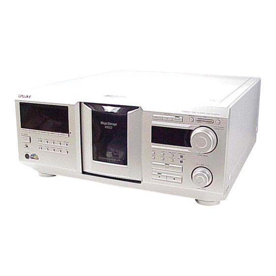
CDP-M400CS SECTION 2 GENERAL This section is extracted from instruction manual. Front Panel q;qaqs qd qfqg qk ql ws wd ejeheg eseae; wk wjwh LOCATION OF PARTS AND CONTROLS 1 1/u (power) button wa FADER button 2 STANDBY indicator ws X-FADE button... -
Page 7: Disassembly
CDP-M400CS SECTION 3 DISASSEMBLY 3-1. DISASSEMBLY FLOW • The equipment can be removed using the following procedure. 3-2.CASE (Page 8) 3-3.MAIN BOARD (Page 8) 3-6.FRONT PANEL 3-4.TRANS BOARD 3-16.BACK PANEL 3-5.IR - IN BOARD ASSEMBLY (Page 9) SECTION (Page 9) -
Page 8: Case
CDP-M400CS Note: Follow the disassembly procedure in the numerical order given. 3-2. CASE 1 three screws (case 3 screw) 2 two screws (case 3 screw) 3 two screws (case 3 screw) 5 case 4 two screws (case 3 screw) 3-3. MAIN BOARD... -
Page 9: Trans Board
CDP-M400CS 3-4. TRANS BOARD 5 screw (BVTP 3 × 8) 7 two screws (PTTWH 3 × 6) 6 bracket (PT) 2 connector (CN602) 3 connector (CN603) 8 TRANS board 4 connector (CN601) 1 connector (CN991) 3-5. IR-IN BOARD 2 IR-IN board 1 two screws (BVTP 3 ×... -
Page 10: Front Panel Assembly
CDP-M400CS 3-6. FRONT PANEL ASSEMBLY 3 connector (CNP503) 7 remove the claw 4 screw (BVTP 3 × 8) 5 two screws (BVTP 3 × 8) 8 remove the claw 9 front panel assembly 6 three screws (BVTP 3 × 8) 3-7. -
Page 11: Cover (Pt), Table (400) Assembly
CDP-M400CS 3-8. COVER (PT), TABLE (400) ASSEMBLY 1 two screws (BVTP 3 × 8) 5 table (400) assembly 2 cover (PT) 3 screw (BVTP 3 × 16) 4 guide (door) Note during re-assembling When re-assembling, align the positions as shown. -
Page 12: Door Sw Board
CDP-M400CS 3-10. DOOR SW BOARD 3 screw (PTPWH 2.6 × 8) 1 screw (PTPWH 2.6 × 8) 5 two screws (BVTP 2.6 × 8) 2 gear (cam) 6 DOOR SW board 4 gear (B) Precaution during the gear (cam) installation... -
Page 13: Base (Door Driving) Assembly
CDP-M400CS 3-11. BASE (DOOR DRIVING) ASSEMBLY 2 three screws (BVTP 3 × 8) 3 cover (table) 7 base (door driving) assembly 4 door assembly 1 connector (CN602) 5 two screws (BVTP 3 × 8) 6 eight screws (BVTP 3 × 8) 3-12. -
Page 14: D.motor Board, Motor Assembly (Door) (M603)
CDP-M400CS 3-13. D.MOTOR BOARD, MOTOR ASSEMBLY (DOOR) (M603) 1 belt (M603) 5 door motor assembly 4 Remove two 3 D.MOTOR board solderings. 2 two screws (BVTP 3 × 8) 3-14. T.SENS BOARD, HOLDER (TABLE SENSOR 400) 2 connector (CN83) 1 four screws (PTPWH 3 ×... -
Page 15: D.sens (Out) Board, D.sens (In) Board
CDP-M400CS 3-15. D.SENS (OUT) BOARD, D.SENS (IN) BOARD 7 screw (PTTWH 3 × 6) 1 screw (PTTWH 3 × 6) 8 D.SENS (IN) board 2 clamp 3 two step screws (T1) 5 screw (PSW 3 × 8) 6 D.SENS (OUT) board 4 bracket (sensor 400) 3-16. -
Page 16: Cd Mechanism, Magnet Assembly
CDP-M400CS 3-17. CD MECHANISM, MAGNET ASSEMBLY 2 three screws (BVTP 3 × 8) 1 three screws (BVTP 3 × 8) 7 CD mechanism 3 bracket (top 400) 5 washer Note during re-assembling When re-assembling, align the positions as shown. 4 magnet assembly... -
Page 17: Loading Sw Board, Lock Sw Board
CDP-M400CS 3-18. LOADING SW BOARD, LOCK SW BOARD 2 screw (BVTP3 × 8) 1 Rotate the pulley (400) in the direction of the arrow fully. 3 Rotate the pulley (400) in the direction of the arrow fully. 7 gear (center) -
Page 18: Cdm Assembly
CDP-M400CS 3-19. CDM ASSEMBLY 1 connector (CN603) 6 CDM assembly 2 connector (CN601) 4 four screws (BVTP 3 × 8) 5 seven screws 3 screw (PSW 3 × 8) (BVTP 3 × 8) 3-20. MOTOR ASSEMBLY (TABLE) (M601), MOTOR ASSEMBLY (LOADING) (M602) -
Page 19: Bu Holder
CDP-M400CS 3-21. BU HOLDER 3 tension spring (F-1) 5 BU holder assy 4 tension spring (F-2) 1 four screws (PTP WH 2.6 × 8) 3-22. BD BOARD, OPTICAL PICK-UP (KSM-213BFN) 9 optical pick-up 7 two vibration 3 Remove two (KSM-213BFN) proof rubbers solderings. -
Page 20: Test Mode
CDP-M400CS SECTION 4 TEST MODE • This unit is provided with several test modes. Details are shown in the following tables. <Menu Method> Turn on the power and press TIME , MEGA CONTROL and 1/u buttons. Rotate the DISC/ALBUM/CHARACTER dial to select any of the following modes. - Page 21 CDP-M400CS SOFT WARE VERSION DISPLAY Special Aging Mode Functions • Software version can be displayed on the fluorescent indicator The aging mode is provided with the following convenient functions tube. 1. Disc setting mode: Procedure: 5 discs are set before setting the aging mode. This mode makes With the power ON, while pressing the TIME and MEGA the setting of these discs more easy.
- Page 22 CDP-M400CS Error Display Error code 2 1. Disc sensor error Code number Contents Error during loading in Error during loading out 1 2 0 With no problem With no problem Disc number with error alternating X : negligible number Error code 3...
- Page 23 CDP-M400CS SHIPMENT MODE ALL LIT MODE • This mode is used for setting the unit to the shipment state. • This mode is used for lighting the whole fluorescent indicator Do not execute it without a proper reason as it erases the tubes and LEDs.
- Page 24 CDP-M400CS ADJ Mode Key and Display Check Mode 1. Turn ON the power of the unit, set disc to disc table, and To set this mode, connect the test point (AFADJ) on the MAIN perform chucking. board to Ground, and connect the power supply plug to the outlet.
-
Page 25: Electrical Adjustment
CDP-M400CS SECTION 5 ADJUSTMENTS Mechanical Adjustments Table Sensor Adjustment 1. Enter the CDM Test mode and select “Mech Adjust” with the Pop Up Mechanism Adjustment JOG dial, and press the dial. 1. Turn on the power and set the disc to number 24. - Page 26 CDP-M400CS Electrical Adjustment RF Level Check oscilloscope Note: BD board 1. CD Block is basically designed to operate without adjustment. Therefore, check each item in order given. TP (RFAC) 2. Use YEDS-18 disc (3-702-101-01) unless otherwise indicated. TP (DVC) 3. Use an oscilloscope with more than 10MΩ impedance.
- Page 27 CDP-M400CS Disc Sensor Adjustment 5. Rotate the DISC/ALBUM/CHARACTER knob in the Be sure to perform this adjustment after sensor adjustment in counterclockwise direction and the disc table starts to rotate MECHANICAL ADJUSTMENT. in the same direction. Check that the waveform at this time is the same as that in step 4.
- Page 28 CDP-M400CS Adjustment Location : [ BD BOARD ] – Conductor Side – IC 101 TP(RF AC) TP(DVC) IC 103 TP(FE1) [ MAIN BOARD ] – Component Side – – Conductor Side – RV501 DISC SENSOR ADJUSTMENT TP(AFADJ) TP(ADJ) IC504 IC501...
-
Page 29: Diagrams
CDP-M400CS SECTION 6 DIAGRAMS • Waveforms • Circuit Boards Location THIS NOTE IS COMMON FOR PRINTED WIRING – BD Board – BOARDS AND SCHEMATIC DIAGRAMS. LED board IC104 yd XO (In addition to this, the necessary note is printed in each block.) MAIN board For Schematic Diagrams. -
Page 30: Block Diagram - Bd Section
CDP-M400CS 6-1. BLOCK DIAGRAM — BD SECTION — OPTICAL PICK-UP BLOCK IC101 IC103 DIGITAL SERVO (KSM-213BFN) RF AMP DIGITAL SIGNAL PROC. IC901 DIGITAL J903 OPTICAL RF AC RFAC D OUT OPTICAL CD IN RFDCO RFDC IC104 Q324 D/A CONV, RFDCI... -
Page 31: Main Section
CDP-M400CS — MAIN SECTION — IC501 (2/2) SYSTEM CONTROL FL701 FL702 FLUORESCENT FLUORESCENT INDICATOR TUBE INDICATOR TUBE IC701 FL DRIVER IC504 FLDATA SRAM DIG1 FLCLK FLT1 DIG15 73 . RESET Q701 DIG16 SEG01 SEG35 AD1(36) D701-709,711, Q551 IC702 712,715 LED DRIVER... -
Page 32: Printed Wiring Board - Bd Section
CDP-M400CS • See page 29 for Circuit Boards Location. 6-2. PRINTED WIRING BOARD — BD SECTION — :Uses unleaded solder. IC150 IC101 IC104 IC105 IC121 (Page 34) • Semiconductor Location Ref. No. Location IC101 IC103 IC104 D-10 IC105 IC121 IC150... -
Page 33: Schematic Diagram - Bd Section
CDP-M400CS • See page 29 for Waveforms. • See page 44, 45 and 46 for IC Block Diagrams. 6-3. SCHEMATIC DIAGRAM — BD SECTION — • See page 47 for IC Pin Function Description. IC B/D MSB710 IC B/D IC B/D... -
Page 34: Printed Wiring Board - Main Section
CDP-M400CS • See page 29 for Circuit Boards Location. 6-4. PRINTED WIRING BOARD — MAIN SECTION — :Uses unleaded solder. KEYBOARD (Page 37) (Page 38) (Page 42) (Page 42) (Page 42) • Semiconductor Location Ref. No. Location D327 D329 D501... -
Page 35: Schematic Diagram - Main Section (1/2)
CDP-M400CS • See page 29 for Waveforms. 6-5. SCHEMATIC DIAGRAM — MAIN SECTION (1/2) — • See page 49 for IC Pin Function Description. DISP BS62LV256SC-70(T) uPD703030BYGF-M13-3BA 4.7k MTZJ-T-72-6.2B TP1008 R1004 C1002 C1009 0.01 TP1007 CN1101 R1006 PH4P No mark:STOP... -
Page 36: Schematic Diagram - Main Section (2/2)
CDP-M400CS 6-6. SCHEMATIC DIAGRAM — MAIN SECTION (2/2) — • See page 45 for IC Block Diagrams. GP1FA550TZ IC B/D No mark:STOP CDP-M400CS... -
Page 37: Printed Wiring Board - Sensor Section
CDP-M400CS • See page 29 for Circuit Boards Location. 6-7. PRINTED WIRING BOARD — SENSOR SECTION — 6-8. SCHEMATIC DIAGRAM — SENSOR SECTION — :Uses unleaded solder. DISC SENSOR IC84 (1/2) CN801 (Page 35) MAIN BOARD CN801 IC83 (Page 34) -
Page 38: Printed Wiring Board - Display Section
CDP-M400CS • See page 29 for Circuit Boards Location. 6-9. PRINTED WIRING BOARD — DISPLAY SECTION — :Uses unleaded solder. (Page 40) (Page 34) IC703 KEYBOARD BOARD MAIN BOARD CN503 IC701 (Page 34) IC702 MODE (13) KEYBOARD • Semiconductor Location... -
Page 39: Schematic Diagram - Display Section
CDP-M400CS 6-10. SCHEMATIC DIAGRAM — DISPLAY SECTION — • See page 44 for IC Block Diagrams. M66310FP IC B/D C703 No mark:STOP CDP-M400CS... -
Page 40: Printed Wiring Board - Jog Section
CDP-M400CS • See page 29 for Circuit Boards Location. 6-11. PRINTED WIRING BOARD — JOG SECTION — :Uses unleaded solder. (Page 38) DISC EJECT 22 23 IC704 (Page 34) (Page 34) CDP-M400CS... -
Page 41: Schematic Diagram - Jog Section
CDP-M400CS 6-12. SCHEMATIC DIAGRAM — JOG SECTION — • See page 44 for IC Block Diagrams. IC B/D /AFP PUSH ENTER No mark:STOP CDP-M400CS... -
Page 42: Printed Wiring Board - Powersection
CDP-M400CS • See page 29 for Circuit Boards Location. 6-13. PRINTED WIRING BOARD — POWER SECTION — :Uses unleaded solder. (Page 34) CN902 IC961 IC941 1-683-728- 1-683-729- CN903 (Page 34) CN901 (Page 34) 1-683-725- • Semiconductor 1-683-726- Location Ref. No. -
Page 43: Schematic Diagram - Power Section
CDP-M400CS 6-14. SCHEMATIC DIAGRAM — POWER SECTION — • See page 45 for IC Block Diagrams. 2.2k 2.2k 2.2k (2/2) AC IN CN902 (Page 36) RELAY V.DISP AU.VEE (2/2) CN901 (Page 36) AU.VCC (1/2) (Page 35) CN903 M.VCC -30V REG -32.8... - Page 44 CDP-M400CS • IC Block Diagrams – DISP Board – IC702 M66310FP – BD Board – IC104 TC94A20F-CX4 BCKIB SDI1 Switch VDDT LRCKIA BCKIA SDIO LRCKO MP3REQ BCKO – JOG Board – IC704 M35500BGP/AFP VDDT VDDM /WIACK 32 31 30 29 28 27 26...
- Page 45 CDP-M400CS – MAIN Board – – TRANS Board – IC931 BA3993F IC941, IC961 LA6510 – – 1 2 3 4 5 6 7 8 9 10 Band Gap – BD Board – IC103 CXA2581N-T4 RW/ROM DC OFST RFDCI – –...
- Page 46 CDP-M400CS IC101 CXD3068Q 59 58 57 56 55 54 53 52 51 50 49 48 47 46 45 44 43 42 41 DVDD2 ASYE DIGITAL ASYMMETRY CORRECTOR DIGITAL DOUT LRCK D/A DIGITAL PCMD INTERFACE DEMODULATOR TES1 TEST1 ERROR DVSS1 CORRECTOR...
- Page 47 CDP-M400CS • IC Pin Function Description BD BOARD IC104 TC94A20F-CX4 (D/A CONVERTER, MP3 DECODER) Pin No. Pin Name Description /RESET Reset input terminal “L”: reset MIMD Microcomputer interface mode selection input “H”: I2C, “L”: TSB (fixed at “H”) /MICS Microcomputer interface chip select signal input (fixed at “L”) /MILP Microcomputer interface latch pulse input (fixed at “L”)
- Page 48 CDP-M400CS Pin No. Pin Name Description PI5/DATA General purpose input/SUBQ interface data input (fixed at “L”) TSTIN/SFSY Terminal for test/SUBQ interface frame sync input (fixed at “L”) FI2/SBSY Flag signal input 2/SUBQ interface block sync input (fixed at “L”) VSSP —...
- Page 49 CDP-M400CS MAIN BOARD IC501 µPD703030BYGF-M13-3BA (SYSTEM CONTROL) Pin No. Pin Name Description FLDATA Data signal output to the fluorescent indicator drivers amd LED driver FLCLK Clock signal output to the fluorescent indicator drivers and LED driver LEDLAT Latch signal output to the LED driver...
- Page 50 CDP-M400CS Pin No. Pin Name Description SRAM write enable signal output SRAM address signal output SRAM data bus 51 to 57 D1 to D7 SRAM data bus BVDD — Power supply (I/O port) BVSS — Ground (I/O port) 60, 61...
-
Page 51: Exploded Views
CDP-M400CS SECTION 7 EXPLODED VIEWS NOTE: • -XX and -X mean standardized parts, so they • Items marked “*” are not stocked since they The components identified by mark 0 or may have some difference from the original are seldom required for routine service. -
Page 52: Chassis Section 1
CDP-M400CS 7-2. CHASSIS SECTION 1 not supplied T911 T901 not supplied not supplied not supplied CNP901 MECHANISM SECTION 1 (CDM62-K1BD46A) CHASSIS SECTION 2 Ref. No. Part No. Description Remark Ref. No. Part No. Description Remark 4-215-968-01 WINDOW (INTERNAL ILLUMINATION) 3-703-249-02 SCREW, S TIGHT, +PTTWH 3X6... -
Page 53: Chassis Section 2
CDP-M400CS 7-3. CHASSIS SECTION 2 not supplied not supplied not supplied MECHANISM SECTION 2 (CDM62-K1BD46A) not supplied Ref. No. Part No. Description Remark Ref. No. Part No. Description Remark 3-703-249-02 SCREW, S TIGHT, +PTTWH 3X6 X-2022-049-1 FOOT ASSY 4-225-873-01 HOLDER (TABLE SENSOR 400) -
Page 54: Front Panel Section
Part No. Description Remark X-2024-235-1 PANEL ASSY, FRONT A-4727-719-A DISP BOARD, COMPLETE 4-977-358-01 CUSHION 3-087-053-01 +BVTP2.6 (3CR) 4-996-698-61 EMBLEM, SONY A-4727-721-A JOG BOARD, COMPLETE 4-226-847-21 KNOB (AMS) 4-982-811-21 HOLDER (FL) 4-226-846-21 KNOB (DISC) * 163 4-929-709-31 GUIDE (FL TUBE) X-4952-642-2 BRACKET (CASE) ASSY... -
Page 55: Mechanism Section 1 (Cdm62-K1Bd46A)
CDP-M400CS 7-5. MECHANISM SECTION 1 (CDM62-K1BD46A) M603 Ref. No. Part No. Description Remark Ref. No. Part No. Description Remark 4-226-827-02 BASE (DOOR DRIVING) 3-701-441-21 WASHER 4-216-093-01 ROLLER 4-226-828-02 GEAR (CAM) 4-216-100-02 HOLDER (POP-UP) 4-226-829-01 GEAR (PULLEY) 4-933-134-11 SCREW (+PTPWH M2.6X8) -
Page 56: Mechanism Section 2 (Cdm62-K1Bd46A)
CDP-M400CS 7-6. MECHANISM SECTION 2 (CDM62-K1BD46A) not supplied not supplied OPTICAL PICK-UP SECTION (BU-K1BD46A) MECHANISM SECTION 3 (CDM62-K1BD46A) Ref. No. Part No. Description Remark Ref. No. Part No. Description Remark 4-216-081-01 SPRING (MG), TORSION X-4950-901-5 HOLDER ASSY, BU 3-701-441-21 WASHER... -
Page 57: Mechanism Section 3 (Cdm62-K1Bd46A)
CDP-M400CS 7-7. MECHANISM SECTION 3 (CDM62-K1BD46A) MECHANISM SECTION 4 (CDM62-K1BD46A) Ref. No. Part No. Description Remark Ref. No. Part No. Description Remark X-4952-499-1 LEVER (LOCK 400) ASSY 4-216-077-01 SPRING (HOLDER FR), TORSION 4-216-067-01 SPRING (CLAMP), COMPRESSION 4-225-871-03 HOLDER (F400) 3-701-441-21 WASHER... -
Page 58: Mechanism Section 4 (Cdm62-K1Bd46A)
CDP-M400CS 7-8. MECHANISM SECTION 4 (CDM62-K1BD46A) not supplied M602 M601 Ref. No. Part No. Description Remark Ref. No. Part No. Description Remark 4-225-865-01 SLIDER (400) 4-225-869-01 GEAR (TABLE 400) X-4952-503-1 LEVER (FULCRUM 400) ASSY 1-683-727-13 L.T.MOTOR BOARD 4-933-134-11 SCREW (+PTPWH M2.6X8) -
Page 59: Optical Pick-Up Section (Bu-K1Bd46A)
CDP-M400CS 7-9. OPTICAL PICK-UP SECTION (BU-K1BD46A) Ref. No. Part No. Description Remark 1-782-817-11 WIRE (FLAT TYPE) (16 CORE) A-4727-735-A BD BOARD, COMPLETE 0 403 A-3328-818-A OPTICAL PICK-UP KSM-213BFN/C2N1 The components identified by Les composants identifiés par mark 0 or dotted line with mark une marque 0 sont critiques 0 are critical for safety. -
Page 60: Electrical Parts List
CDP-M400CSNW-E53 SECTION 8 ELECTRICAL PARTS LIST NOTE: • Due to standardization, replacements in the • Items marked “*” are not stocked since they When indicating parts by reference number, parts list may be different from the parts are seldom required for routine service. please include the board name. - Page 61 CDP-M400CS D.MOTOR D.SENS (IN) D.SENS (OUT) DISP Ref. No. Part No. Description Remark Ref. No. Part No. Description Remark FB111 1-216-864-11 SHORT CHIP R232 1-216-817-11 METAL CHIP 1/10W FB251 1-414-594-11 INDUCTOR, FERRITE BEAD R233 1-216-817-11 METAL CHIP 1/10W FB291 1-216-864-11 SHORT CHIP...
- Page 62 CDP-M400CS DISP DOOR SW IR-IN Ref. No. Part No. Description Remark Ref. No. Part No. Description Remark C791 1-162-286-31 CERAMIC 220PF < SWITCH > C792 1-162-294-31 CERAMIC 0.001uF S741 1-771-349-21 SWITCH, KEYBOARD (TOP ARTIST 1) < CONNECTOR > S742 1-771-349-21 SWITCH, KEYBOARD (TOP ARTIST 2)
- Page 63 CDP-M400CS KEYBOARD L.T.MOTOR Ref. No. Part No. Description Remark Ref. No. Part No. Description Remark A-4727-721-A JOG BOARD, COMPLETE R775 1-247-807-31 CARBON 1/4W R794 1-247-807-31 CARBON 1/4W ******************** 4-929-709-31 GUIDE (FL TUBE) < ROTARY ENCODER > < CAPACITOR > RE701...
- Page 64 CDP-M400CS LOADING SW LOCK SW MAIN Ref. No. Part No. Description Remark Ref. No. Part No. Description Remark 1-683-730-13 LED BOARD C404 1-126-965-91 ELECT 22uF C405 1-126-965-91 ELECT 22uF ********** C407 1-126-960-11 ELECT < CAPACITOR > C410 1-164-159-11 CERAMIC 0.1uF...
- Page 65 CDP-M400CS MAIN Ref. No. Part No. Description Remark Ref. No. Part No. Description Remark CN502 1-784-739-11 CONNECTOR, FFC 17P Q425 8-729-900-65 TRANSISTOR DTA144ES CN503 1-785-332-11 PIN, CONNECTOR (LIGHT ANGLE) 6P Q426 8-729-029-46 TRANSISTOR DTA143ESA CN505 1-785-335-11 PIN, CONNECTOR (LIGHT ANGLE) 9P...
- Page 66 CDP-M400CS MAIN T.SENS TRANS Ref. No. Part No. Description Remark Ref. No. Part No. Description Remark R426 1-247-807-31 CARBON 1/4W R941 1-249-389-11 CARBON 1/4W R439 1-247-895-00 CARBON 470K 1/4W R942 1-249-385-11 CARBON 1/4W R440 1-249-409-11 CARBON 1/4W R943 1-249-421-11 CARBON 2.2K...
- Page 67 CDP-M400CS TRANS Ref. No. Part No. Description Remark Ref. No. Part No. Description Remark C942 1-109-953-11 ELECT 2.2uF < RESISTOR > C943 1-164-159-11 CERAMIC 0.1uF R901 1-247-831-91 CARBON 1/4W C951 1-136-173-00 MYLAR 0.47uF R902 1-249-429-11 CARBON 1/4W C961 1-136-165-00 MYLAR 0.1uF...
- Page 68 CDP-M400CS Ref. No. Part No. Description Remark MISCELLANEOUS ************** 1-469-854-11 CORE, FERRITE 1-782-817-11 WIRE (FLAT TYPE) (16 CORE) 0 403 A-3328-818-A OPTICAL PICK-UP KSM-213BFN/C2N1 0 CNP901 1-783-820-21 CORD, POWER M601 A-4672-895-A MOTOR (400) ASSY (TABLE) M602 A-4672-895-A MOTOR (400) ASSY (LOADING)
- Page 69 CDP-M400CS MEMO...
-
Page 70: Revision History
CDP-M400CS REVISION HISTORY Clicking the version allows you to jump to the revised page. Also, clicking the version at the upper right on the revised page allows you to jump to the next revised page. Ver. Date Description of Revision...
Need help?
Do you have a question about the CDP-M400CS and is the answer not in the manual?
Questions and answers