Table of Contents
Advertisement
Advertisement
Chapters
Table of Contents

Related Manuals for E-FLITE Mini Funtana


Summary of Contents for E-FLITE Mini Funtana
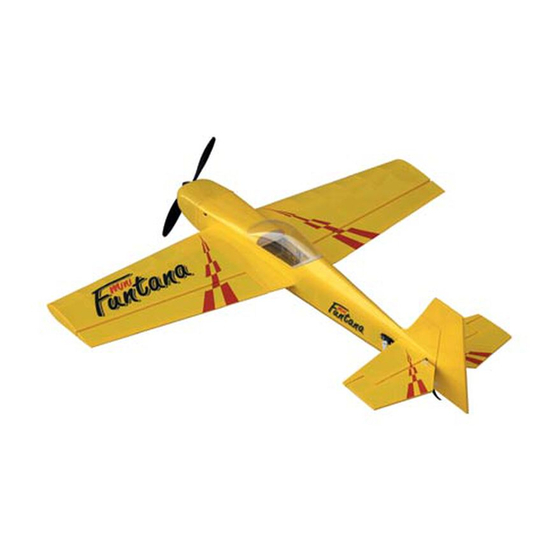
- Page 1 Mini Funtana Assembly Manual...
-
Page 2: Table Of Contents
Introduction ............. 2 Thank you for purchasing the E-flite Mini Funtana 3D Specifications ..........3 ARF Park Flyer. The Mini Funtana is an extreme 3D Additional Required Equipment ......3 aerobatic electric park flyer, based on the proven Additional Tools and Adhesives ......3 abilities of the popular Hangar 9 FuntanaS airplanes. -
Page 3: Additional Required Equipment
Paper towels Li-Po Battery: 11.1V 1800–2100 3-Cell (EFLB1025, Wax paper 150–180 grit sandpaper EFLB1035 or THP21003S) Speed Control: E-Flite 20 amp brushless ESC (EFLA311) or Castle 25 amp brushless ESC (CSEPHX25) Motor/Gearbox/Propeller 6.6:1 gearbox (included) (EFLM221) 12x6 Propeller (included) (EFLP1260) -
Page 4: Optional Parts
Before Starting Assembly who manage throttle appropriately. This motor will Before beginning the assembly of your Mini Funtana provide even better vertical performance at the 3D, remove each part from its bag for inspection. -
Page 5: Contents Of Kit/Parts Layout
Contents of Kit/Parts Layout Large Replacement Parts: Small Replacement Parts: Wing Set w/ Ailerons EFL2076 Wheel Set EFL2056 Fuselage w/Hatch EFL2077 Pushrod Set EFL2079 Tail Set EFL2078 Fiberglass Wheel Pant Set EFL2084 Carbon Fiber Main Gear EFL2080 Wing Tube EFL2085 Fuselage Hatch EFL2081 Hook and Loop Tape... -
Page 6: Warranty Information
Warranty Information Please note that once assembly of the model has been started, you must contact Horizon Hobby, Inc. Horizon Hobby, Inc. guarantees this kit to be free directly regarding any warranty question. Please from defects in both material and workmanship at the do not contact your local hobby shop regarding date of purchase. -
Page 7: Landing Gear Installation
Landing Gear Installation 1. Slide the 2mm x 25mm screw through one of the wheels. Thread a 2mm nut onto the screw. Required Parts Slide a 2mm washer onto the screw. This will all fit inside the wheel pant. Fuselage Carbon main gear Tail skid... - Page 8 2. Fit the assembly from Step 1 into the wheel 4. Drill 1/8" (3mm) holes in the tail for the pant. Use a 2mm washer and nut to attach the tail skid. wheel to the lower hole on the landing gear. Note: Use threadlock on both nuts to prevent them from loosening during flight.
- Page 9 5. Glue the tail skid into position using 6. Attach the landing gear using a 3/32" hex Medium CA. wrench, two 4-40 x 1/2" socket head screws and two #4 washers (black).
- Page 10 7. Place the fuselage on its wheels and position the 8. Secure the location of the wheel pants using wheel pants parallel to the work surface. Drill a 2mm x 6mm wood screws and a small phillips hole through the landing gear into each wheel screwdriver.
-
Page 11: Aileron Hinging
Aileron Hinging 1. Locate the positions for the hinges. Drill a 3/32" (2.5mm) hole in the center of each slot. Required Parts This creates a tunnel for the CA, allowing the CA to penetrate into the hinge better, bonding Wing (left and right) Aileron (left and right) the hinges more securely. - Page 12 2. Slide four hinges into the slits in the wing. Note: Do not use CA accelerator during the hinging process. The CA must be allowed to Center the slot in the hinge with the hole drilled soak into the hinge to provide the best bond. in Step 1.
- Page 13 3. Slide the aileron into position. Check to make 4. Firmly grasp the wing and aileron and gently sure it can move without interference at the pull on the aileron to ensure the hinges are wing root. Remove the T-pins and apply secure and cannot be pulled apart.
-
Page 14: Aileron Servos And Linkages
Aileron Servos and Linkages 5. Work the aileron up and down several times to work in the hinges and check for Required Parts proper movement. Wing panel (right and left) Micro control connector (2) 2mm x 4mm screw (2) 4"... - Page 15 Use string to secure the servo lead and extension to prevent them from unplugging in flight. Note: We suggest using the Large Arms w/ Screws (JRPA212) on all JR® servos for the Mini Funtana. Replace all existing arms before installing the servos.
- Page 16 3. Secure the aileron servo using the screws 4. Use a hobby knife to enlarge the center provided with the servo. hole in the control horn to fit the 4" (100mm) long aileron pushrod wire. 5. Repeat Steps 1 through 4 for the other wing panel.
- Page 17 6. Use 6-minute epoxy to attach the control horn 7. Attach the micro control connector to both to the aileron. Attach the control horns for both servo arms. Be sure to use the included retainer the right and left ailerons at this time. to secure the micro control connector to the servo arms.
-
Page 18: Wing Installation
Wing Installation 8. Turn on the radio system and center the aileron trim and stick. Make sure the aileron servo is Required Parts operating properly using the transmitter. Slide the pushrod wire through the micro connector. Fuselage Wing (right and left) Install the servo arm 90-degrees to the servo. - Page 19 2. Remove the hatch from the fuselage. Slide 3. Slide the remaining wing panel into position. the wing panel with tube into position on the Secure the panels using 4-40 x 1/2" socket fuselage. head screws with #4 washers (silver) using a 3/32"...
-
Page 20: Stabilizer And Elevator
Stabilizer and Elevator 2. Measure from the stab tip to the wing tip. Adjust the stab until the measurements are equal. Required Parts Fuselage w/wing installed Stabilizer Elevator CA hinge (4) Required Tools and Adhesives Hobby knife Felt-tipped pen Ruler T-pins Thin CA... - Page 21 3. View the airframe from the rear and make sure 4. Double-check the adjustments from Steps 1 the wing and stab are parallel. If not, lightly through 3. Use a felt-tipped pen to trace the sand the stab saddle until they are. outline of the fuselage onto the top and bottom of the stabilizer.
- Page 22 5. Use a sharp hobby knife to cut the covering 6. Hinge the elevator and stabilizer, using the slightly inside the lines drawn. Be very careful same process as described in Aileron Hinging. not to cut into the underlying wood, as this will Use 4 hinges for this process.
- Page 23 7. Slide the stab and elevator back into position. Again, check the alignment and make sure everything lines up. Wick Thin CA into the joint between the fuselage and stabilizer. Make sure to glue both top and bottom. Do not use accelerator—...
-
Page 24: Rudder And Fin
Rudder and Fin 2. Remove the covering from the bottom of the fin using the same technique used for the stabilizer. Required Parts Fuselage Rudder CA hinge (3) Required Tools and Adhesives Hobby knife Thin CA Felt-tipped pen Square ... - Page 25 3. Position the fin back onto the fuselage. Use a 4. Use thin CA to glue the fin to the fuselage. square to check the alignment between the fin and stabilizer. Lightly sand the bottom of the fin until the alignment is correct.
- Page 26 6. Attach the rudder using three CA hinges. Use 5. Use a sharp hobby knife to cut a slot in the aft the technique as described in Aileron Hinging end of the fuselage for the lower rudder hinge. for this procedure.
-
Page 27: Motor Installation
Required Tools and Adhesives the gears. See the instructions included with your 6-minute epoxy Hobby knife E-flite gearbox for more helpful tips on gear mesh 150–200 grit sandpaper and motor installation. Proper gear mesh is extremely important for ... - Page 28 2. Attach the motor to the gearbox using screws 3. Locate the motor support stick. Use 6-minute provided with the motor. epoxy to glue the support to the two formers at the front of the fuselage.
- Page 29 4. Slide the gearbox into position on the motor support stick. Trial fit the cowl in position at this time to be sure the gearbox, motor and propeller fit in position without interference with the front of the cowl. Next, trial fit the propeller onto the gearbox hex nut.
-
Page 30: Rudder And Elevator Servos
Rudder and Elevator Servos 1. Install the grommets and brass eyelets in the elevator servo. Secure a 9" (230mm) servo Required Parts extension to the servo. Mount the elevator servo using the hardware provided with the servo. Fuselage Micro control horn w/backplate (2) "... -
Page 31: Phillips Screwdriver (Small)
4. Install the micro control connector onto the 3. Attach the micro control horn to the elevator servo arm. Pass the elevator pushrod elevator using the control horn backplate and wire through the connector. With the radio 6-minute epoxy. on and elevator trim centered, center the elevator. -
Page 32: Receiver, Battery And Esc Install
Receiver, Battery and ESC Install 5. Repeat Steps 1 through 4 for the rudder servo and linkage using the 5 " (145mm) Required Parts pushrod wire. Fuselage Battery Hook and loop tape (2) Receiver 75mm x 20mm x 2mm light ply 35mm x 20mm x 7mm balsa block Brushless speed control Required Tools and Adhesives... - Page 33 1. Trim the 75mm x 20mm x 2mm light ply to fit Note: Do not cut the receiver antenna, as this will greatly reduce the range of the radio system. in position between the fuselage longerons. You will need to trim the length once the Center of Gravity has been determined.
- Page 34 Note: When mounting the EFLA311 ESC, a 3. Install the battery in the fuselage using the 35mm x 20mm x 7mm balsa block is required to remaining piece of hook and loop material. space the ESC away from the fuselage side. The battery must be mounted close to the firewall for proper Center of Gravity.
-
Page 35: Canopy Install
Canopy Install 2. Position the canopy. Trace the outline of the canopy onto the canopy hatch using a Required Parts felt-tipped pen. Fuselage Canopy Required Tools and Adhesives Canopy glue Wax paper Felt-tipped pen 150–220 grit sandpaper 1. Place a piece of wax paper between the rear of the canopy hatch and fuselage. - Page 36 3. Lightly sand the inside edge of the canopy 4. Glue the canopy to the hatch using canopy where it contacts the hatch. Also sand the hatch glue. Tape the canopy into position until the inside the line drawn in the last step. glue cures.
-
Page 37: Cowling Install
Cowling Install 1. Slide the cowl onto the fuselage. Center the motor shaft in the opening. Check to make Required Parts sure the propeller and spinner will not interfere Fuselage Cowling with the front of the cowl and there is adequate 12x6 propeller Spinner clearance. - Page 38 Note: It is very important that you check to be 3. Press the spinner into position on the sure the propeller is balanced before installing gearbox shaft. onto the shaft. An unbalanced propeller may strip the gear. When installing the propeller, please do not over tighten the 3mm lock nut.
-
Page 39: Control Throws
Control Throws Low rate (U/D) High Rate (U/D) Elevator: 3/4" (19mm) " (58mm) 1. Turn on the transmitter and receiver of your Mini Ailerons: 1" (25mm) " (48mm) Funtana. Check the movement of the rudder Rudder: " (95mm) " (95mm) using the transmitter. -
Page 40: Center Of Gravity
An important part of preparing the aircraft for flight is allow the Mini Funtana to really cut loose. It is properly balancing the model. best to increase the exponential values used to maintain a smooth feel. -
Page 41: Range Test Your Radio
Range Test Your Radio 2. Double-check that all controls (aileron, elevator, rudder and throttle) move in the correct direction. 1. Before each flying session, be sure to range check your radio. This is accomplished by turning on your transmitter with the antenna ... -
Page 42: 2004 Official Ama National Model Aircraft Safety Code
2004 Official AMA 5) I will not fly my model unless it is identified with my name and address or AMA number, on or in the National Model Aircraft Safety Code model. (This does not apply to models while being GENERAL flown indoors.) 1) I will not fly my model aircraft in sanctioned events,... - Page 43 3) At all flying sites a straight or curved line(s) must 6) For Combat, distance between combat engagement be established in front of which all flying takes place line and spectator line will be 500 feet per cubic inch with the other side for spectators. Only personnel of engine displacement.
- Page 44 © 2004 Horizon Hobby, Inc. 4105 Fieldstone Road Champaign, Illinois 61822 (877) 504-0233 www.horizonhobby.com 7011...
Need help?
Do you have a question about the Mini Funtana and is the answer not in the manual?
Questions and answers