Table of Contents
Troubleshooting

Related Manuals for Hobart 120CU20


Summary of Contents for Hobart 120CU20
-
Page 1: Illustrated Parts List
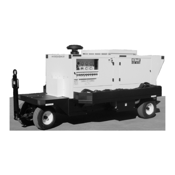
OM-2228 05/06/13– Original 10/15/13- Rev A Operation and Maintenance Manual with Illustrated Parts List 120CU20 120 kVA, 3 Phase, 115/200 Volt, 400 Hz. Generator Set Series 500120 ITW GSE Group Hobart Ground Systems Palmetto, Florida 34221 U.S.A. - Page 3 In the event any component manufacturer has warranted its component to HOBART and will not deal directly with a first user then HOBART will cooperate with the first user in the presentation of a claim to such manufacturer. Under NO circumstances does HOBART assume any liability for any warranty claim against or warranty work done by or in behalf of any manufacturer of the foregoing components.
- Page 5 OM-2228 / Operation and Maintenance Manual 120CU20 / Series 500120 / 400 Hz. Generator Set Record of Change. Rev. Release Date. Description. May 06, 2013 1. New – spec roll for new starter, wire harness, etc. to create Deluxe and Standard models.
- Page 6 OM-2228 / Operation and Maintenance Manual 120CU20 / Series 500120 / 400 Hz. Generator Set This page is intentionally left blank. October 15, 2013 Revision Log Page 2...
- Page 7 OM-2228 / Operation and Maintenance Manual 120CU20 / Series 500120 / 400 Hz. Generator Set Safety Warnings and Cautions. WARNING ELECTRIC SHOCK can KILL. Do not touch live electrical parts. ELECTRIC ARC FLASH can injure eyes, burn skin, cause equipment damage, and ignite combustible material.
- Page 8 OM-2228 / Operation and Maintenance Manual 120CU20 / Series 500120 / 400 Hz. Generator Set the equipment grounding conductor (lead) to the third live wire of the 3-phase line, as this makes the equipment frame electrically HOT, which can cause a fatal shock.
- Page 9 OM-2228 / Operation and Maintenance Manual 120CU20 / Series 500120 / 400 Hz. Generator Set completely fill tank, because heat from the equipment may cause fuel expansion overflow. Remove all spilled fuel IMMEDIATELY, including any that penetrates the unit. After clean-up, open equipment doors and blow fumes away with compressed air.
- Page 10 OM-2228 / Operation and Maintenance Manual 120CU20 / Series 500120 / 400 Hz. Generator Set This page is intentionally left blank. October 15, 2013 Safety Warnings Page 4...
- Page 11 120CU20 / Series 500120 / 400 Hz. Generator Set Introduction This manual contains operation and maintenance information for a 120CU20, 400 Hz Generator Set manufactured by ITW GSE Group, Hobart Ground Systems, Palmetto, Florida 34221. This manual is not intended to be a textbook on electricity or electronics. Its primary purpose is to provide information and instructions to experienced operators, electricians, and mechanics who have never operated this equipment.
- Page 12 OM-2228 / Operation and Maintenance Manual 120CU20 / Series 500120 / 400 Hz. Generator Set If you have any questions concerning your Hobart Ground Systems equipment, immediately contact our Service Department by mail, telephone, FAX, or E-Mail. Write: Hobart Ground Systems...
- Page 13 OM-2228/ Operation and Maintenance Manual 120CU20 / Series 500120 / 400 Hz. Generator Set Table of Contents. Chapter 1 Description/Operation. Chapter-Section/Page# Section 1 Description. 1-1/1 General 1-1/1 Optional Equipment - Appendix A 1-1/1 Orientation 1-1/1 Special Features 1-1/2 Canopy 1-1/2...
- Page 14 OM-2228/ Operation and Maintenance Manual 120CU20 / Series 500120 / 400 Hz. Generator Set Section 2 Maintenance Procedures. 2-2/1 General 2-2/1 Lubrication 2-2/1 Servicing The Air Cleaner 2-2/6 Engine Fuel 2-2/7 Engine Fuel System 2-2/7 Engine Cooling System 2-2/10 Generator Maintenance...
- Page 15 OM-2228/ Operation and Maintenance Manual 120CU20 / Series 500120 / 400 Hz. Generator Set Chapter 3 Overhaul / Major Repair. Chapter-Section/Page# Section 1 Exciter Armature. 3-1/1 General 3-1/1 Exciter Armature 3-1/2 Exciter Armature Replacement 3-1/3 Exciter Armature Installation 3-1/6 Section 2 Dual Bearing Flexible Coupling.
-
Page 16: Wet Stacking
OM-2228/ Operation and Maintenance Manual 120CU20 / Series 500120 / 400 Hz. Generator Set Section 3 Illustrated Parts List. 4-3/1 Explanation of Parts List Arrangement 4-3/1 Symbols and Abbreviations 4-3/1 Figure 1: General Assembly 4-3/2 Figure 2: Labels and Reflectors... -
Page 17: Section 1 Description
Chapters 1 through 5 of this Operation and Maintenance Manual identifies only the “stripped down” version of the 120CU20 generator set. A list of optional equipment that makes this manual unique to the generator set that you have purchased, appears in Appendix A. - Page 18 OM-2228 / Operation and Maintenance Manual 120CU20 / Series 500120 / 400 Hz. Generator Set 4) Special Features. The generator set has special features that are described more fully, under the assemblies in which they appear. a) Protective Monitoring. The protective monitoring system receives signals from the fault sensing units in the generator output circuit and functions to cause the load to be disconnected from the generator if an abnormal condition of voltage, frequency, or load develops.
- Page 19 OM-2228 / Operation and Maintenance Manual 120CU20 / Series 500120 / 400 Hz. Generator Set 6) Specifications a) Physical Specifications Basic Unit Physical With Trailer (Fixed Mount) Length 116 in. (2946 mm) 160 in. (4064 mm) w/ tow bar up Width 59 in.
- Page 20 OM-2228 / Operation and Maintenance Manual 120CU20 / Series 500120 / 400 Hz. Generator Set d) DC Output Specifications (with optional TR unit). Output Power Rating 17.1 kW Output Voltage 28.5 VDC Load Capacity (Continuous) 600 A Current Limiting Capability...
- Page 21 OM-2228 / Operation and Maintenance Manual 120CU20 / Series 500120 / 400 Hz. Generator Set g) Normal Operating Characteristics. Engine oil pressure (warm and at 45 PSI (310 kPa) minimum rated speed 2000 RPM) 50 to 65 PSI (345 to 448 kPA) typical Engine coolant temperature 180 to 200º...
- Page 22 OM-2228 / Operation and Maintenance Manual 120CU20 / Series 500120 / 400 Hz. Generator Set c) Engine-cooling fan The engine fan is designed to blow air outward through the radiator, rather than pulling the air inward as a conventional fan does.
- Page 23 OM-2228 / Operation and Maintenance Manual 120CU20 / Series 500120 / 400 Hz. Generator Set Engine faults. The following is a table listing faults, which may occasionally occur. Column two of the table explains what happens in the engine’s circuitry when the fault occurs, and column three tells how to return the generator set to service once the problem is solved.
- Page 24 OM-2228 / Operation and Maintenance Manual 120CU20 / Series 500120 / 400 Hz. Generator Set 1. Control Panel 6. Emergency Stop Switch (S28) 2. Operator’s Push-button Panel 7. Exhaust Outlet (Not Shown) 3. Output Cable Location 8. Canopy 4. Front Axle Assembly 9.
- Page 25 OM-2228 / Operation and Maintenance Manual 120CU20 / Series 500120 / 400 Hz. Generator Set 1. Radiator 7. 12 VDC Batteries (BT1, BT2) 2. Charge-Air-Cooler 8. Generator 3. Cummins QSB6.7 Engine 9. Pre-Fuel Filter 4. Air Cleaner 10. Rear Axle 5.
- Page 26 OM-2228 / Operation and Maintenance Manual 120CU20 / Series 500120 / 400 Hz. Generator Set 1. Dual Output Power Module 6. Top and Bottom Fan Shroud 2. Exhaust Muffler Shield 7. Alternator Fan/Belt Guard 3. Exhaust Muffler 8. Engine Cooling Fan 4.
- Page 27 OM-2228 / Operation and Maintenance Manual 120CU20 / Series 500120 / 400 Hz. Generator Set Air Cleaner Service Indicator Figure 4: Air Cleaner and Service Indicator Generator. The 400 Hz generator is a brushless, revolving field, three-phase, alternating current type. The generator set covered by this manual is a dual-bearing type.
- Page 28 OM-2228 / Operation and Maintenance Manual 120CU20 / Series 500120 / 400 Hz. Generator Set 1. Engine Coolant Temperature Gauge (M24) 7. AC Generator Voltmeter (M2) 2. Running Time Meter (M4) 8. AC Generator Ammeter (M1) 3. Battery Voltmeter (M5) 9.
- Page 29 OM-2228 / Operation and Maintenance Manual 120CU20 / Series 500120 / 400 Hz. Generator Set (1) Panel lights and panel light push-button switch (S74) Meters are lighted from inside the control panel. The “LAMPS” push-button switch controls the lights. (2) Engine hour meter (M4) The hour meter is electrically driven from the 12-volt DC battery system.
- Page 30 OM-2228 / Operation and Maintenance Manual 120CU20 / Series 500120 / 400 Hz. Generator Set (8) “ENGINE STOP” push-button switch (S76). When the “ENGINE STOP” push-button switch is pressed, the red indicator will glow. Then a 3 - 5 minute delay will occur to permit the turbo and other engine components to cool evenly. After the delay, power is disconnected from the engine ECM causing the engine to shut down.
- Page 31 OM-2228 / Operation and Maintenance Manual 120CU20 / Series 500120 / 400 Hz. Generator Set (15) Front LED Display (A5). The front LED display indicates, which voltage (A-N, A-B, etc…) and amperage are shown on the meters and whether “EF BY-PASS” is present or bypassed. This “EF BY-PASS” indicator serves to warn the operator that if the plug interlock system was by-passed any exposed cable may be live.
- Page 32 OM-2228 / Operation and Maintenance Manual 120CU20 / Series 500120 / 400 Hz. Generator Set Control Box Interior Components. 1. Control Box Wrapper 7. +5, -12 VDC Power Supply (PS1) 2. Engine Specific PC Board [ESB] (A1) 8. Circuit Breaker Support Bracket 3.
- Page 33 OM-2228 / Operation and Maintenance Manual 120CU20 / Series 500120 / 400 Hz. Generator Set (2) Regulated-diagnostic switch (located on the REG). When the “REGULATED/DIAGNOSTIC” switch is in the “REGULATED” (down) position, the generator output voltage is regulated by the PC board for 115/200 VAC output to an aircraft.
- Page 34 OM-2228 / Operation and Maintenance Manual 120CU20 / Series 500120 / 400 Hz. Generator Set (5) Engine Interface PC Board [EIB] (A2). The EIB is common between all engine models and monitors coolant temperature, oil pressure, battery voltage, and fuel tank level monitoring. The EIB is also responsible for the monitoring the warning switches for high coolant temperature, low oil pressure, high air restriction, and low coolant level (optional).
- Page 35 OM-2228 / Operation and Maintenance Manual 120CU20 / Series 500120 / 400 Hz. Generator Set Figure 9: Engine Specific PC Board. (7) Voltage regulator PC board [REG] (A4). Figure 10: Voltage Regulator PC Board. October 15, 2013 Chapter 1-1 Page 19...
- Page 36 OM-2228 / Operation and Maintenance Manual 120CU20 / Series 500120 / 400 Hz. Generator Set This voltage regulator PC board is designed to provide voltage regulation for a three-phase, four- wire, 115/200-volt, 400-Hz brushless alternator. This regulator provides field excitation power as required to meet varying alternator load conditions to hold the alternator voltage constant.
- Page 37 OM-2228 / Operation and Maintenance Manual 120CU20 / Series 500120 / 400 Hz. Generator Set Figure 11: Transformer-Rectifier PC Board Figure 12: Control System Power Source. October 15, 2013 Chapter 1-1 Page 21...
- Page 38 OM-2228 / Operation and Maintenance Manual 120CU20 / Series 500120 / 400 Hz. Generator Set 9) Power Module Panel Assembly. The power module panel assembly, sometimes referred to as the contactor panel, is located at the left front of the machine under the control box. The panel assembly provides a means of connecting and disconnecting generator output to and from the load (aircraft).
- Page 39 OM-2228 / Operation and Maintenance Manual 120CU20 / Series 500120 / 400 Hz. Generator Set Current Transformers Generator Output Leads Output Contactors Figure 13: Output Power Module Components. October 15, 2013 Chapter 1-1 Page 23...
- Page 40 OM-2228 / Operation and Maintenance Manual 120CU20 / Series 500120 / 400 Hz. Generator Set 10) Cold Weather Starting System (BH1) The intake air heater, located on the intake manifold, is used for starting the engine at very cold temperatures and reduces the white smoke associated with a cold start. This cold weather starting system is a fully automatic once engaged by the operator (Chapter 1, Section 3).
- Page 41 OM-2228 / Operation and Maintenance Manual 120CU20 / Series 500120 / 400 Hz. Generator Set 11) Transformer-Rectifier Assembly Components. The T-R provides a regulated output voltage of 28.5V DC. Input power is provided to the DC components from the 115/200 volt, 400 Hz generator set, through an input contactor. The output contactor provides DC power to the load.
- Page 42 OM-2228 / Operation and Maintenance Manual 120CU20 / Series 500120 / 400 Hz. Generator Set 1. Transformer Assembly (T401) 5. DC Inductor / Filter Assembly (L401) 2. Heat Sink / Diode Assembly (CR402-CR407) 6. Pre-Load Resistors (R402-R404) 3. Input Contactor (K401) 7.
- Page 43 OM-2228 / Operation and Maintenance Manual 120CU20 / Series 500120 / 400 Hz. Generator Set Section 2 Preparation for: Use, Storage, or Shipping. 1) Preparation for Use. a) Inspection/Check. Inspect the unit thoroughly prior to operation. (1) Remove blocking, banding, ties, and other securing material.
- Page 44 OM-2228 / Operation and Maintenance Manual 120CU20 / Series 500120 / 400 Hz. Generator Set Engine lubricating oil level The oil gauge rod has “H” high mark and “L” low-level marks to indicate the operating lubrication oil supply. Oil level should be kept as near the high mark as possible, without going over it.
- Page 45 OM-2228 / Operation and Maintenance Manual 120CU20 / Series 500120 / 400 Hz. Generator Set To install AC output cables proceed as follows: (1) Open control box door of the generator set and remove the lower panel. (2) Remove Plexiglas cover in front of the power module assembly.
- Page 46 OM-2228 / Operation and Maintenance Manual 120CU20 / Series 500120 / 400 Hz. Generator Set Output Cables Contactor Figure 3 Output Cable Connection Clamp Output Cables Figure 4 Lower Panel Assembly October 15, 2013 Chapter 1-2 Page 4...
- Page 47 Place containers of moisture- absorbing chemicals (Hobart Part No. 76A-1354-001) in the unit before packaging. The unit may be stored for long periods with no special preparation if it is possible to operate the engine once each week.
- Page 48 OM-2228 / Operation and Maintenance Manual 120CU20 / Series 500120 / 400 Hz. Generator Set (2) Start the engine and operate under full load until coolant temperature has reached at least 176ºF (80ºC). (3) While the engine is running, ensure that normal operating controls are in good working condition before shutdown and storage.
-
Page 49: Section 3 Operation
OM-2228 / Operation and Maintenance Manual 120CU20 / Series 500120 / 400 Hz. Generator Set Section 3 Operation. 1) General. This section contains information and instructions for the safe and efficient operation of the equipment. Operating instructions are presented in step-by-step sequence of procedures to be followed in supplying 400-Hz power. - Page 50 OM-2228 / Operation and Maintenance Manual 120CU20 / Series 500120 / 400 Hz. Generator Set 1. Engine Coolant Temperature Gauge (M24) 7. AC Generator Voltmeter (M2) 2. Running Time Meter (M4) 8. AC Generator Ammeter (M1) 3. Battery Voltmeter (M5) 9.
- Page 51 OM-2228 / Operation and Maintenance Manual 120CU20 / Series 500120 / 400 Hz. Generator Set b) Normal Engine Starting Procedures. Engine starting procedures are outlined below. The engine’s operating controls and monitoring instruments are illustrated in Figure 1. CAUTION Refer to operating instructions in the engine manufacturer’s operation manual, when starting engine for the first time.
- Page 52 OM-2228 / Operation and Maintenance Manual 120CU20 / Series 500120 / 400 Hz. Generator Set CAUTION To eliminate the possibility of wet stacking (See Appendix A), DO NOT allow the engine to idle for long periods. c) Failed Starting Procedure.
- Page 53 OM-2228 / Operation and Maintenance Manual 120CU20 / Series 500120 / 400 Hz. Generator Set WARNING NEVER disconnect the output cable while power is being delivered. Output contactors must be open prior to removal of the cable from the aircraft.
- Page 54 OM-2228 / Operation and Maintenance Manual 120CU20 / Series 500120 / 400 Hz. Generator Set 3) DC Operating Procedure (optional). This section describes the operation of the optional DC unit. The DC output voltage value, which is controlled by a potentiometer on the Transformer-Rectifier Board (TRB), need only be set once. The voltage level will remain the same for all future operations, even when the unit is shut down or the battery is disconnected.
- Page 55 OM-2228 / Operation and Maintenance Manual 120CU20 / Series 500120 / 400 Hz. Generator Set Chapter 2 Service and Troubleshooting. Section 1 Maintenance Inspection/Check. 1) General. To make certain the generator set is always ready for operation, it must be inspected and maintained regularly and systematically so that defects may be discovered and corrected before they result in serious damage to components, or failure of the equipment.
- Page 56 OM-2228 / Operation and Maintenance Manual 120CU20 / Series 500120 / 400 Hz. Generator Set Hourly Interval 50-150 1000 1500 2000 Calendar Interval Once Daily 3 Mo. 6 Mo. 1 Yr. 1.5 Yr. 2 Yr. Symbol Engine Change Air Cleaner Cartridge...
- Page 57 OM-2228 / Operation and Maintenance Manual 120CU20 / Series 500120 / 400 Hz. Generator Set Hourly Interval 50-150 1000 1500 2000 Calendar Interval Once Daily 3 Mo. 6 Mo. 1 Yr. 1.5 Yr. 2 Yr. Symbol Engine (continued) Flush and Change Coolant Check Fan Mounting Spring &...
- Page 58 OM-2228 / Operation and Maintenance Manual 120CU20 / Series 500120 / 400 Hz. Generator Set b) “AR” Checks and Operations (As Required). (1) Engine. Change Air Cleaner. Replace the air filter when the fault code meter shows the “air” code. These filters should not be washed because washing breaks down the material inside the filters.
- Page 59 OM-2228 / Operation and Maintenance Manual 120CU20 / Series 500120 / 400 Hz. Generator Set d) “A” Checks and Operations (10 Hours or Daily). (1) Engine. Check Crankcase Oil Level. CAUTION DO NOT overfill. DO NOT operate the engine with oil level below the lower bar or above the upper bar on the dipstick.
- Page 60 OM-2228 / Operation and Maintenance Manual 120CU20 / Series 500120 / 400 Hz. Generator Set Water Drain Check Fault Code Meter. At each daily start-up, observe the fault code meter on the control panel. If the display shows “air”, change the air filter. See Section 2-4 for other fault codes.
- Page 61 OM-2228 / Operation and Maintenance Manual 120CU20 / Series 500120 / 400 Hz. Generator Set (3) Electrical (400 Hz System). Check Output Cables and Connector. Check the output cable and plug connection for damaged insulation and contacts each time the connector is detached from the aircraft.
- Page 62 OM-2228 / Operation and Maintenance Manual 120CU20 / Series 500120 / 400 Hz. Generator Set “C” Checks and Operations (500 Hours or 6 Months). (1) Engine. Check Engine and Generator Mounts. CAUTION An unstable or loosely mounted engine can create hazardous environment and may damage equipment.
- Page 63 OM-2228 / Operation and Maintenance Manual 120CU20 / Series 500120 / 400 Hz. Generator Set g) “D” Checks and Operations (1000 Hours or 1 Year). (1) Engine. Check Fan Hub and Drive Pulley. Inspect for loose bolts or worn features. Tighten bolts and replace parts if necessary. Refer to the engine manufacturer’s operations and maintenance manual for assistance and the...
- Page 64 OM-2228 / Operation and Maintenance Manual 120CU20 / Series 500120 / 400 Hz. Generator Set CAUTION 1. If a cleaning compound is used, select one that is free from acid and will not remove paint. 2. Protect (or remove) all electrical accessories, such as voltage regulator, alternator, and electrical wiring.
- Page 65 OM-2228 / Operation and Maintenance Manual 120CU20 / Series 500120 / 400 Hz. Generator Set “F” Checks and Operations (2000 Hours or 2 Years). (1) Engine. Check Vibration Damper. Check vibration damper for looseness, wobble, chunking and streaking. Also verify the hub bolts are tightened to the engine manufacturer’s specifications.
- Page 66 OM-2228 / Operation and Maintenance Manual 120CU20 / Series 500120 / 400 Hz. Generator Set (3) The lamp chart lists all lamps with their location and identifying trade number in table below. (4) The circuit breaker chart lists all circuit breakers with their location, size, and type.
- Page 67 OM-2228 / Operation and Maintenance Manual 120CU20 / Series 500120 / 400 Hz. Generator Set Section 2 Maintenance Procedures. 1) General. A suggested maintenance schedule was provided in Section 1 of this Servicing Chapter. Each step of the schedule was also covered in general in Section 1. This Section covers maintenance in more detail, where necessary.
- Page 68 OM-2228 / Operation and Maintenance Manual 120CU20 / Series 500120 / 400 Hz. Generator Set (2) Oil specification. Engine lubricating oil, recommended by the engine manufacturer, is identified by an API (American Petroleum Institute) classification designation. The manufacturer does not recommend any specific brand of lubricating oil.
- Page 69 OM-2228 / Operation and Maintenance Manual 120CU20 / Series 500120 / 400 Hz. Generator Set Item Maintenance Required Check oil level daily or after every 10 hours of use. Change oil and the oil filter Lube Oil. after the first 50 to 150 hours of use, then at 500 hour or 6 month intervals thereafter.
- Page 70 OM-2228 / Operation and Maintenance Manual 120CU20 / Series 500120 / 400 Hz. Generator Set Symbol Name Specification Notes Grease, General Purpose MIL-G-3545 Excludes those of sodium or soda soap thickness. Lubricants Chart While oil is draining, change the oil filter element. See instructions below.
- Page 71 OM-2228 / Operation and Maintenance Manual 120CU20 / Series 500120 / 400 Hz. Generator Set Clean the drain plug and install when engine oil has completely drained. Torque the drain plug to 50 foot-pounds (68 Nm). Use the oil refill tube to refill the crankcase with new, clean oil that meets engine manufacturer’s recommendations.
- Page 72 OM-2228 / Operation and Maintenance Manual 120CU20 / Series 500120 / 400 Hz. Generator Set 3) Servicing the Air Cleaner. This air filter element is a disposable type which, when dirty, may be discarded. A definite time schedule for cleaning or changing the air cleaner cannot be determined because of varying operating conditions.
- Page 73 OM-2228 / Operation and Maintenance Manual 120CU20 / Series 500120 / 400 Hz. Generator Set 4) Engine Fuel. a) How to select Fuel—Quality. The quality of fuel oil used in the diesel engine is a major factor in engine performance and life. Fuel oil must be clean, completely distilled, stable and non-corrosive.
- Page 74 OM-2228 / Operation and Maintenance Manual 120CU20 / Series 500120 / 400 Hz. Generator Set b) Fuel Water Separator. The equipment manufacturer has mounted a fuel water separator on the inner wall of the canopy. Its function is to remove foreign material and extract water from the fuel before it enters the fuel lift pump.
- Page 75 OM-2228 / Operation and Maintenance Manual 120CU20 / Series 500120 / 400 Hz. Generator Set Water Drain Figure 4 Fuel/Water Separator/Lubricity Fuel Filter. (1) Changing the lubricity fuel filter. Replacement lubricity filter part number: • Hobart: 286897-031 • Cummins: FS20022 The lubricity filter must be change after every 500 hours of operation in order for the fuel filter to continue adding the proper amounts of the lubricity additive into the fuel system.
- Page 76 OM-2228 / Operation and Maintenance Manual 120CU20 / Series 500120 / 400 Hz. Generator Set Screw in the new fuel filter “snug”. Check that the cartridge is seated correctly against the gasket and tighten with a final half turn. Open fuel valve.
- Page 77 OM-2228 / Operation and Maintenance Manual 120CU20 / Series 500120 / 400 Hz. Generator Set b) Radiator Cap. (1) General. A pressure relief valve is built into the radiator cap. It is designed to open at a pressure of approximately 15 psi (103.4 Kpa).
- Page 78 OM-2228 / Operation and Maintenance Manual 120CU20 / Series 500120 / 400 Hz. Generator Set (2) Selecting antifreeze. Select a permanent type antifreeze known to be satisfactory for use with chromate corrosion resistor. When it is not known if the antifreeze is satisfactory for use with chromate resistor, check with local engine manufacturer’s representative for a list of compatible antifreezes.
- Page 79 OM-2228 / Operation and Maintenance Manual 120CU20 / Series 500120 / 400 Hz. Generator Set g) Filling the Cooling System. The preparation and monitoring of coolant in liquid-cooled engines is especially important because corrosion, cavitations, and freezing can lead to engine damage. For coolant system protection details see the engine manufacturer’s operations manual.
- Page 80 OM-2228 / Operation and Maintenance Manual 120CU20 / Series 500120 / 400 Hz. Generator Set 7) Generator Maintenance. The 400 Hz generator requires no maintenance or service other than periodic cleaning. The unit is brushless and has bearings that are permanently lubricated and sealed.
- Page 81 OM-2228 / Operation and Maintenance Manual 120CU20 / Series 500120 / 400 Hz. Generator Set Section 3 Adjustment/Test. 1) General. These adjustments and test procedures are applicable to testing and adjusting the generator set after major repair, major parts replacements, or overhaul.
- Page 82 OM-2228 / Operation and Maintenance Manual 120CU20 / Series 500120 / 400 Hz. Generator Set 1. Engine Coolant Temperature Gauge (M24) 7. AC Generator Voltmeter (M2) 2. Running Time Meter (M4) 8. AC Generator Ammeter (M1) 3. Battery Voltmeter (M5) 9.
- Page 83 OM-2228 / Operation and Maintenance Manual 120CU20 / Series 500120 / 400 Hz. Generator Set b) Operational Test Procedures (1) Start the engine according to the instructions in Section 1-3. (2) Check operation of engine instruments; voltmeter, coolant temperature indicator, oil pressure gauge and hour meter (all shown in Figure 1).
- Page 84 OM-2228 / Operation and Maintenance Manual 120CU20 / Series 500120 / 400 Hz. Generator Set Figure 2: Control Box Interior Components. October 15, 2013 Chapter 2-3 Page 4...
- Page 85 OM-2228 / Operation and Maintenance Manual 120CU20 / Series 500120 / 400 Hz. Generator Set c) Testing the No. 1 Output Circuit. (1) Place the EF Bypass switch in “BYPASS / OFF” position and turn the EF signal “ON” on the load bank.
- Page 86 OM-2228 / Operation and Maintenance Manual 120CU20 / Series 500120 / 400 Hz. Generator Set (5) Place the No. 1 EF bypass switch to “BYPASS / OFF” position. The No. 1 load contactor should open at once and the yellow indicating light within the No. 1 load contactor push button switch should go off and the fault code display should also read “EF 1”, indicating a EF warning.
- Page 87 OM-2228 / Operation and Maintenance Manual 120CU20 / Series 500120 / 400 Hz. Generator Set (11) In EF bypass mode, apply 1/3 to 1/2 load at the load bank and allow the unit to run for 15 to 30 minutes. Observe operation of all monitoring instruments.
- Page 88 OM-2228 / Operation and Maintenance Manual 120CU20 / Series 500120 / 400 Hz. Generator Set In any LINE-TO-LINE position, voltmeter reading should be 200 volts when the LED under the voltmeter indicates two of the phases being checked. (4) Check accuracy of frequency meter Connect a master frequency meter of known accuracy to the terminals of the frequency meter.
- Page 89 OM-2228 / Operation and Maintenance Manual 120CU20 / Series 500120 / 400 Hz. Generator Set If the under voltage circuit performs satisfactorily, return unit to normal operation by adjusting output voltage coarse adjustment potentiometer for normal output voltage, pressing the “TEST/REST”...
- Page 90 OM-2228 / Operation and Maintenance Manual 120CU20 / Series 500120 / 400 Hz. Generator Set (8) Check over-frequency circuit and fault code display. At some frequency value 420 Hz to 440 Hz, after 5 seconds, the over frequency sensing circuit should signal the over-frequency circuit protective monitor to OPEN the load contactor and display “70.22”...
- Page 91 OM-2228 / Operation and Maintenance Manual 120CU20 / Series 500120 / 400 Hz. Generator Set Figure 6: Engine Interface PC Board. (4) The fault code will flash in the following sequence: First, a “Check Engine” (yellow) lamp will flash. There will be a short 1- or 2-second pause after which the number of the recorded fault code will flash in the “Engine Stop”...
- Page 92 OM-2228 / Operation and Maintenance Manual 120CU20 / Series 500120 / 400 Hz. Generator Set g) Re-checking the entire unit after testing. (1) With the engine running at normal rated speed, check the entire unit for vibration and for any parts that may have become loosened during the above checks.
- Page 93 OM-2228 / Operation and Maintenance Manual 120CU20 / Series 500120 / 400 Hz. Generator Set Figure 7: Voltage Regulator PC Board. (1) Output Voltage Adjustment. Adjust Voltage Control. The output voltage, at which the generator is regulated, is adjustable by the fine voltage- adjustment potentiometer (Figure 7).
- Page 94 OM-2228 / Operation and Maintenance Manual 120CU20 / Series 500120 / 400 Hz. Generator Set Adjust Line-Drop Compensation. Adjustment of line-drop compensation is made with the line-drop compensation potentiometer. Turning the potentiometer knob clockwise increases the magnitude of the compensation, and turning the potentiometer knob counterclockwise decreases the magnitude (A graduated nameplate for specified cable lengths is included for quick reference).
- Page 95 OM-2228 / Operation and Maintenance Manual 120CU20 / Series 500120 / 400 Hz. Generator Set d) Engine Accessories Adjustment. (1) Alternator and fan belt adjustment: refer to Section 2-1 and engine manufacturer’s manual. 4) Generator and Exciter Test. The generator fields and exciter stator may be tested with a Kelvin bridge. This is a double-bridge type instrument required for the very low resistances encountered in this test.
- Page 96 OM-2228 / Operation and Maintenance Manual 120CU20 / Series 500120 / 400 Hz. Generator Set 5) Diode Test. Test values for diodes are not given here because they could be misleading. Test values may vary even between diodes of the same part number, rating, and manufacturer. General instructions for testing diodes are as follows: a) Disconnect exciter windings from diode lead(s).
- Page 97 OM-2228 / Operation and Maintenance Manual 120CU20 / Series 500120 / 400 Hz. Generator Set (3) Current Limiting / Soft Starting Control. Press the “STARTNG CURRENT” push button to activate the current limiting and set the limit to 1500 A.
- Page 98 OM-2228 / Operation and Maintenance Manual 120CU20 / Series 500120 / 400 Hz. Generator Set The contactor should open in 10 seconds. The fault code meter will read “70.30” Discontinue power delivery and let the cables cool for 2-3 minutes.
- Page 99 OM-2228 / Operation and Maintenance Manual 120CU20 / Series 500120 / 400 Hz. Generator Set Section 4 Troubleshooting Procedures 1) General The Troubleshooting Chart and Fault Code Chart located in this section cover the common faults and malfunctions that you may find during operation or maintenance of this equipment. The charts may not list all faults and malfunctions that may occur.
- Page 100 OM-2228 / Operation and Maintenance Manual 120CU20 / Series 500120 / 400 Hz. Generator Set 4) 400 Hz. Test Values Although test values are provided throughout the troubleshooting chart, additional information and values are given here. Generator output voltage at maximum voltage regulator potentiometer setting:...
- Page 101 OM-2228 / Operation and Maintenance Manual 120CU20 / Series 500120 / 400 Hz. Generator Set 9) GPU Control Monitoring The GPU control system performs complete diagnostic testing and continuous monitoring of all critical circuits and operating electrical values. If the control system senses a problem with one of the circuits or if any of the electrical values exceeds its safe operating limit, the control system will shut the GPU down, or may allow the GPU to continue operation depending on the severity of the condition.
- Page 102 OM-2228 / Operation and Maintenance Manual 120CU20 / Series 500120 / 400 Hz. Generator Set (3) Engine Idle Mode When the engine has been started, the engine will begin in the idle mode. The “ENGINE START” push-button will flash indicating the engine is in the idle mode.
- Page 103 OM-2228 / Operation and Maintenance Manual 120CU20 / Series 500120 / 400 Hz. Generator Set (1) Warning Warning faults have no effect on the operation of the GPU. An example is an intake air restriction fault due to a dirty filter. Although the GPU continues to operate, the fault appears on the fault code display.
-
Page 104: Fault Codes
OM-2228 / Operation and Maintenance Manual 120CU20 / Series 500120 / 400 Hz. Generator Set Command Fault 70.67 Fault Codes Figure 1 Fault Meter Display d) Operation Monitoring While applying power to an aircraft, the GPU continually monitors all critical circuits and operating electrical values. - Page 105 OM-2228 / Operation and Maintenance Manual 120CU20 / Series 500120 / 400 Hz. Generator Set Record Designator Record Number - 1 21 Fault Record Number “121” Figure 2 Fault Meter Display (Fault Record Number) (4) Release the “TEST/RESET” push-button. The display alternates between the fault record number (See Figure 2) and the fault code (See Figure 1).
- Page 106 OM-2228 / Operation and Maintenance Manual 120CU20 / Series 500120 / 400 Hz. Generator Set 1. Engine Coolant Temperature Gauge (M24) 7. AC Generator Voltmeter (M2) 2. Running Time Meter (M4) 8. AC Generator Ammeter (M1) 3. Battery Voltmeter (M5) 9.
- Page 107 OM-2228 / Operation and Maintenance Manual 120CU20 / Series 500120 / 400 Hz. Generator Set Figure 4 Control Box Interior Components. October 15, 2013 Chapter 2-4 Page 9...
-
Page 108: Engine Controls
OM-2228 / Operation and Maintenance Manual 120CU20 / Series 500120 / 400 Hz. Generator Set Trouble, Symptom, Probable Cause. Test, Check, and/or Remedy. Condition. Engine Controls. 1. The engine will not a. Battery discharged or Check the voltage across batteries. - Page 109 OM-2228 / Operation and Maintenance Manual 120CU20 / Series 500120 / 400 Hz. Generator Set Trouble, Probable Cause. Test, Check, and/or Remedy. Symptom, Condition. Engine Controls (continued). 2. Engine will not a. Low battery output. Check the battery and recharge or replace start.
- Page 110 OM-2228 / Operation and Maintenance Manual 120CU20 / Series 500120 / 400 Hz. Generator Set Trouble, Symptom, Condition Probable Cause Test, Check, and/or Remedy Engine Controls (continued) 6. Engine starts but a. Shutdown circuit may Restart the engine and observe oil pressure gauge.
- Page 111 OM-2228 / Operation and Maintenance Manual 120CU20 / Series 500120 / 400 Hz. Generator Set Trouble, Symptom, Probable Cause. Test, Check, and/or Remedy. Condition. Generator Excitation Circuits. 1. No (or low) a. Defective generator or On REG place Regulated/ Diagnostic switch in generator output excitation circuit.
- Page 112 OM-2228 / Operation and Maintenance Manual 120CU20 / Series 500120 / 400 Hz. Generator Set Trouble, Symptom, Condition. Probable Cause. Test, Check, and/or Remedy. Load Contactor Operating Circuits. Output 1: Contactor K1, Push-button switch S75. Output 2: Contactor K201, Push-button switch S275.
- Page 113 OM-2228 / Operation and Maintenance Manual 120CU20 / Series 500120 / 400 Hz. Generator Set Trouble, Symptom, Condition. Probable Cause. Test, Check, and/or Remedy. Load Contactor Operating Circuit (Continued). 2. Load contactor closes when a. The plug interlock EF circuit on...
- Page 114 OM-2228 / Operation and Maintenance Manual 120CU20 / Series 500120 / 400 Hz. Generator Set Trouble, Symptom, Probable Cause. Test, Check, and/or Remedy. Condition. Protective Circuit NOTE: Protective monitoring is not completely functional until the load contactor is CLOSED. Since it is not advisable to vary voltages for test purposes while delivering power to an aircraft, the GPU should be connected to a load bank for trouble shooting protective circuits.
- Page 115 OM-2228 / Operation and Maintenance Manual 120CU20 / Series 500120 / 400 Hz. Generator Set Trouble, Symptom, Probable Cause. Test, Check, and/or Remedy. Condition. Protective Circuit (continued). 3. Load contactor opens a. Frequency adjust Set frequency adjust switch to DISABLE during power delivery.
- Page 116 OM-2228 / Operation and Maintenance Manual 120CU20 / Series 500120 / 400 Hz. Generator Set Trouble, Symptom, Probable Cause. Test, Check, and/or Remedy. Condition. Generator. 1. No (or low) voltage output a. Shorted diode in exciter Check diodes in accordance with Section rectifier (CR2).
- Page 117 OM-2228 / Operation and Maintenance Manual 120CU20 / Series 500120 / 400 Hz. Generator Set Trouble, Symptom, Condition. Probable Cause. Test, Check, and/or Remedy. T-R Controls and Components. 1. Input AC and Output DC a. Defective push-button switch At rated speed, measure the contactor will not close when “DC...
- Page 118 OM-2228 / Operation and Maintenance Manual 120CU20 / Series 500120 / 400 Hz. Generator Set Trouble, Symptom, Condition Probable Cause Test, Check, and/or Remedy T-R Controls and Components (continued) 2. (continued) e. Interlock signal not being Be sure the output cable is received from the aircraft.
-
Page 119: Troubleshooting Table
OM-2228 / Operation and Maintenance Manual 120CU20 / Series 500120 / 400 Hz. Generator Set Troubleshooting Table GPU Commands Name Description code 00. _ _ Invalid Command 01. _ _ ENGINE SELF-TEST CMD All boards test the communication between each other. - Page 120 OM-2228 / Operation and Maintenance Manual 120CU20 / Series 500120 / 400 Hz. Generator Set Troubleshooting Table Faults Fault Name Possible Cause(s) Corrective Action code Check for obstructions. EIB AIR RESTRICTION Air filter is obstructed or dirty. Change air filter cartridge or...
- Page 121 OM-2228 / Operation and Maintenance Manual 120CU20 / Series 500120 / 400 Hz. Generator Set Faults Fault Name Possible Cause(s) Corrective Action code REG OUTPUT UNDER FREQ Defective engine ECM Replace engine ECM. _ _.23 FAULT Defective REG board Replace REG board.
- Page 122 OM-2228 / Operation and Maintenance Manual 120CU20 / Series 500120 / 400 Hz. Generator Set Faults Fault Name Possible Cause(s) Corrective Action code OVERTEMP FAULT Defective thermal switch Replace switch. TRB INPUT CONTACTOR Defective input contactor. Replace input contactor. _ _.46 FAULT Defective TRB board.
- Page 123 OM-2228 / Operation and Maintenance Manual 120CU20 / Series 500120 / 400 Hz. Generator Set Chapter 3 Overhaul/Major Repair. Section 1. Exciter Armature. 1) General. This section provides information and instructions for removal and installation of the exciter armature used on this generator set. Through design improvements, the exciter and rear main bearing can be removed without removing the generator from the generator set.
- Page 124 OM-2228 / Operation and Maintenance Manual 120CU20 / Series 500120 / 400 Hz. Generator Set 3. Diode Mounting Plate 1. Exciter Core Flange 2. Exciter Core Lamination 4. Silicon Diode Figure 2 Exciter Armature. The exciter armature is mounted on the rear portion of the main generator armature shaft, which extends rearward beyond the rear generator bearing into the exciter housing (See Figure 1).
- Page 125 OM-2228 / Operation and Maintenance Manual 120CU20 / Series 500120 / 400 Hz. Generator Set The exciter armature is mounted on the main generator armature shaft with a 3/8-inch square machine key that is held in place by a key retainer, and an M12-1.75 hex head cap screw in the center of the diode mounting plate.
- Page 126 OM-2228 / Operation and Maintenance Manual 120CU20 / Series 500120 / 400 Hz. Generator Set (4) Disconnect the two rectifier-to-generator field leads, which are attached to the rectifier mounting plate with ring terminals. (5) Take EXERCISE CARE to prevent damage to leads. Remove kinks in the two generator leads as much as possible before starting removal operation (The exciter armature will be sliding over these leads.).
- Page 127 OM-2228 / Operation and Maintenance Manual 120CU20 / Series 500120 / 400 Hz. Generator Set WARNING To prevent personal injury, keep fingers and hands clear of generator assembly until the armature is block into place to prevent rotation. Attempt to loosen exciter armature on shaft by rotating it slightly back and forth. If armature cannot be loosened by hand, use two M10-1.5 hex-head bolts as shown in Figure 4 to force...
- Page 128 OM-2228 / Operation and Maintenance Manual 120CU20 / Series 500120 / 400 Hz. Generator Set CAUTION Pay close attention to field leads while pulling exciter armature from shaft. Make CERTAIN that the leads stay in the 1/2" keyway. One mechanic should watch them constantly while another operates the puller.
- Page 129 OM-2228 / Operation and Maintenance Manual 120CU20 / Series 500120 / 400 Hz. Generator Set b) Exciter Armature Installation. (1) If the exciter armature-to-generator shaft fit is such that the exciter armature may be pushed on by hand, push it on very slowly while another mechanic carefully watches and pulls field leads through hole in the exciter armature diode mounting plate.
- Page 130 OM-2228 / Operation and Maintenance Manual 120CU20 / Series 500120 / 400 Hz. Generator Set (3) Install the Machine Key. Clean the machine key thoroughly. All mounting surfaces must be free of rust, corrosion, oil, grease, etc. Apply LOCQUIC primer, No. 47-56 grade T to SIDES of machine key. Do not over prime. A thin film is best.
- Page 131 Hobart Ground Systems as Part Number 288481. This assembly is illustrated in Figure 1. The primary function of this assembly is to couple a Hobart 2000 RPM Generator to a Diesel engine. The flexible coupling assembly compensates for slight misalignment between the engine and the generator, due to manufacturing tolerances.
- Page 132 OM-2228 / Operation and Maintenance Manual 120CU20 / Series 500120 / 400 Hz. Generator Set Figure 2 Access to Coupling Bolts (for removal or installation). b) Remove Coupling Assembly. WARNING To prevent personal injury, keep fingers and hands clear of generator assembly until the armature is block into place to prevent rotation.
- Page 133 OM-2228 / Operation and Maintenance Manual 120CU20 / Series 500120 / 400 Hz. Generator Set Check the shaft for any damage or deformation where the coupling was mounted on it. Check rubber bushing alignment to make sure that the dimension illustrated in Figure 4 is maintained.
- Page 134 Bushing Kit. A bushing kit is available from Hobart for replacing the rubber bushing only in the coupling assembly. However, it should be noted that the finished coupling assembly must be balanced to 1/2 inch-ounce (360 mg-m) minimum, which may be a problem in the field.
- Page 135 OM-2228 / Operation and Maintenance Manual 120CU20 / Series 500120 / 400 Hz. Generator Set (3) Shake the container of lubricant (supplied with kit) vigorously and poor it into a small shallow dish. (4) Roll a bushing in the lubricant to coat it thoroughly. Press it into a socket (from the chamfered end) to the dimension shown in Figure 4.
- Page 136 OM-2228 / Operation and Maintenance Manual 120CU20 / Series 500120 / 400 Hz. Generator Set CAUTION Do not rotate the armature while this block is installed. (5) Install the key in the shaft keyway. (6) Place the bushing in the hub over the installed key, and install the coupling assembly on the shaft, with the bushing approximately flush with the end of the shaft.
- Page 137 OM-2228 / Operation and Maintenance Manual 120CU20 / Series 500120 / 400 Hz. Generator Set 6) Run-in and Periodic Check. a) Mount the engine-generator assembly in a suitable test area and operate it for a 2-hour run-in. b) Shut down the engine after 2 hours and re-torque all coupling bolts to 85 foot-pounds (115 N-m) to compensate for normal torque relaxation.
- Page 138 OM-2228 / Operation and Maintenance Manual 120CU20 / Series 500120 / 400 Hz. Generator Set Figure 4 Bushing Installation. October 15, 2013 Chapter 3-2 Page 8...
- Page 139 OM-2228 / Operation and Maintenance Manual 120CU20 / Series 500120 / 400 Hz. Generator Set Figure 5 Assembly Procedure. Figure 6 Measure from mounting face to adapter ring. October 15, 2013 Chapter 3-2 Page 9...
- Page 140 OM-2228 / Operation and Maintenance Manual 120CU20 / Series 500120 / 400 Hz. Generator Set Figure 7 Measuring from Mounting Face to Bushing. October 15, 2013 Chapter 3-2 Page 10...
- Page 141 OM-2228 / Operation and Maintenance Manual 120CU20 / Series 500120 / 400 Hz. Generator Set Section 3 Generator Assembly. 1) General. This section provides information and instructions for removal and installation of the generator set. 2) Generator Assembly Removal. a) Procedure for Gaining Access to the Generator.
- Page 142 OM-2228 / Operation and Maintenance Manual 120CU20 / Series 500120 / 400 Hz. Generator Set b) Removing the generator Assembly. (1) Remove the four 5/8 - 11 x 4-1/2 bolts that mount the generator assembly to the frame of the generator set.
- Page 143 OM-2228 / Operation and Maintenance Manual 120CU20 / Series 500120 / 400 Hz. Generator Set Top Charge Air Cooler Hood Power Module Cover Bottom Charge Air Cooler Hood Power Module Assembly Bottom Charge Air Cooler Hood Gasket Control Box Assembly...
- Page 144 OM-2228 / Operation and Maintenance Manual 120CU20 / Series 500120 / 400 Hz. Generator Set 3) Generator Assembly Installation. Installation of a generator assembly is essentially a reversal of the procedure for removal of the generator assembly: the re-mounting of the generator assembly to the frame of the generator set, and the remounting of the assemblies that were removed to gain access to the generator assembly.
-
Page 145: Section 1 Introduction
1) General. The Illustrated Parts List identifies, describes, and illustrates main assemblies, subassemblies, and detail parts of an Engine-Generator Set manufactured by ITW GSE Group, Hobart Ground Systems. 2) Purpose. The purpose of this list is to provide parts identification and descriptive information to maintenance and provisioning personnel for use in provisioning, requisitioning, purchasing, storing, and issuing of spare parts. - Page 146 120CU20 / Series 500120 / 400 Hz. Generator Set (2) FACTORY PART NUMBER Column. All part numbers appearing in this column are Hobart numbers. In all instances where the part is a purchased item, the vendor’s identifying five-digit code and his part number will appear in the “NOMENCLATURE”...
- Page 147 OM-2228 / Operation and Maintenance Manual 120CU20 / Series 500120 / 400 Hz. Generator Set Section 2 Manufacturer's Codes. 1) Explanation of Manufacturer’s (Vendor) Code List. The following list is a compilation of vendor codes with names and addresses for suppliers of purchased parts listed in this publication.
- Page 148 OM-2228 / Operation and Maintenance Manual 120CU20 / Series 500120 / 400 Hz. Generator Set Code. Vendor’s Name and Address. Code. Vendor’s Name and Address. 1DL99 Fleetguard Inc. 2N562 Power Transmission Sales Inc. Div. of Cummins Engine Company 531 Washington 311 N.
- Page 149 OM-2228 / Operation and Maintenance Manual 120CU20 / Series 500120 / 400 Hz. Generator Set Code. Vendor’s Name and Address. Code. Vendor’s Name and Address. 39TH9 Motion Industries Inc. 57347 Wall Industries Inc. 8580 Industry Park Dr. 5 Watson Brook Rd.
- Page 150 OM-2228 / Operation and Maintenance Manual 120CU20 / Series 500120 / 400 Hz. Generator Set Code. Vendor’s Name and Address. Code. Vendor’s Name and Address. 71400 Cooper Bussmann Inc. 81703 Mulberry Metal Products Inc. 114 Old State Road 2199 Stanley Terrace...
- Page 151 OM-2228 / Operation and Maintenance Manual 120CU20 / Series 500120 / 400 Hz. Generator Set Section 3 Illustrated Parts List. 1) Explanation of Parts List Arrangement. The parts list is arranged so that the illustration will appear on a left-hand page and the applicable parts list will appear on the opposite right-hand page.
- Page 152 OM-2228 / Operation and Maintenance Manual 120CU20 / Series 500120 / 400 Hz. Generator Set Fixed Mount Bracket Figure 1 General Assembly. October 15, 2013 Chapter 4-3 Page 2...
- Page 153 OM-2228 / Operation and Maintenance Manual 120CU20 / Series 500120 / 400 Hz. Generator Set FIGURE HOBART UNITS NOMENCLATURE ITEM NO. PART NO. PER ASSY. 286956 Draw Bar 282667 Bracket, Pivot Arm Assembly 282727 …Cover, Plate, Pivot Arm 280763 …Plate, Bearing 408781-001 …Pin, Spring...
- Page 154 OM-2228 / Operation and Maintenance Manual 120CU20 / Series 500120 / 400 Hz. Generator Set Figure 2 Labels and Reflectors. October 15, 2013 Chapter 4-3 Page 4...
- Page 155 OM-2228 / Operation and Maintenance Manual 120CU20 / Series 500120 / 400 Hz. Generator Set FIGURE HOBART UNITS NOMENCLATURE. ITEM NO. PART NO. PER ASSY. 289842-001 Label, www.hobartsystems.com 408665-002 Reflector, Amber (V12662 #B491A) 287466 Label, Emergency Stop 288300 Plate, Legend, Emergency Stop...
- Page 156 OM-2228 / Operation and Maintenance Manual 120CU20 / Series 500120 / 400 Hz. Generator Set Figure 3 Frame Assembly. October 15, 2013 Chapter 4-3 Page 6...
- Page 157 OM-2228 / Operation and Maintenance Manual 120CU20 / Series 500120 / 400 Hz. Generator Set UNITS FIGURE HOBART NOMENCLATURE. ITEM NO. PART NO. ASSY. 288879 Panel, Front Canopy 287738-025 …Insulation, Top (Option) 287738-029 …Insulation, Left Center (Option) 287738-030 …Insulation, Left (Option) 287738-031 …Insulation, Right Center...
- Page 158 OM-2228 / Operation and Maintenance Manual 120CU20 / Series 500120 / 400 Hz. Generator Set Figure 4 Canopy Assembly. October 15, 2013 Chapter 4-3 Page 8...
- Page 159 OM-2228 / Operation and Maintenance Manual 120CU20 / Series 500120 / 400 Hz. Generator Set UNITS FIGURE HOBART NOMENCLATURE ITEM NO. PART NO. ASSY. 287701 Door, Assembly (see Figure 5) 288880 Door, Control Box (see Figure 5) 288544 Panel, Support Door 287738-020 …Insulation, Panel, Door Support(Option)
- Page 160 OM-2228 / Operation and Maintenance Manual 120CU20 / Series 500120 / 400 Hz. Generator Set Figure 5 Canopy Doors October 15, 2013 Chapter 4-3 Page 10...
- Page 161 OM-2228 / Operation and Maintenance Manual 120CU20 / Series 500120 / 400 Hz. Generator Set FIGURE HOBART UNITS NOMENCLATURE ITEM NO. PART NO. PER ASSY. 287701 Door, Assembly 287738-001 …Insulation, Noise, Door (Option) 288880 Door, Control Box 287738-028 …Insulation, Noise, Door (Option)
- Page 162 OM-2228 / Operation and Maintenance Manual 120CU20 / Series 500120 / 400 Hz. Generator Set 17 10 Right Side Left Side Figure 6 Internal Components. October 15, 2013 Chapter 4-3 Page 12...
- Page 163 OM-2228 / Operation and Maintenance Manual 120CU20 / Series 500120 / 400 Hz. Generator Set FIGURE HOBART UNITS PER NOMENCLATURE ITEM NO. PART NO. ASSY. Left Side Control Box Assembly Ref. (See Figures 7 & 8) 289593-001 …Mount, Rubber (V5P059 #51225)
- Page 164 OM-2228 / Operation and Maintenance Manual 120CU20 / Series 500120 / 400 Hz. Generator Set Figure 7 Door control Panel Assembly. October 15, 2013 Chapter 4-3 Page 14...
- Page 165 OM-2228 / Operation and Maintenance Manual 120CU20 / Series 500120 / 400 Hz. Generator Set FIGURE HOBART UNITS NOMENCLATURE ITEM NO. PART NO. PER ASSY. Door, Control Panel, Assembly – AC only 289018-002 289018-004 Door, Control Panel, Assembly – with DC...
- Page 166 OM-2228 / Operation and Maintenance Manual 120CU20 / Series 500120 / 400 Hz. Generator Set Figure 8 Control Box Interior Components. October 15, 2013 Chapter 4-3 Page 16...
- Page 167 OM-2228 / Operation and Maintenance Manual 120CU20 / Series 500120 / 400 Hz. Generator Set FIGURE HOBART UNITS NOMENCLATURE ITEM NO. PART NO. PER ASSY. Control Box – AC only 289019-001 289019-002 Control Box – with DC 288994 Side, Left, Control Box...
- Page 168 OM-2228 / Operation and Maintenance Manual 120CU20 / Series 500120 / 400 Hz. Generator Set Common Parts Lamps and Meter Select Pushbuttons All Other Push-buttons Figure 9 Pushbutton Switches. October 15, 2013 Chapter 4-3 Page 18...
- Page 169 OM-2228 / Operation and Maintenance Manual 120CU20 / Series 500120 / 400 Hz. Generator Set FIGURE UNITS PER PART NO. DESCRIPTION ITEM NO. ASSY. 289012-002 Pushbutton Switch Box – AC only 289012-004 Pushbutton Switch Box – with DC 289004 Switch Panel 289014 …Switch Panel Label...
- Page 170 OM-2228 / Operation and Maintenance Manual 120CU20 / Series 500120 / 400 Hz. Generator Set Figure 10 400 Hz. Power Module Assembly. October 15, 2013 Chapter 4-3 Page 20...
- Page 171 OM-2228 / Operation and Maintenance Manual 120CU20 / Series 500120 / 400 Hz. Generator Set FIGURE HOBART UNITS NOMENCLATURE ITEM NO. PART NO. PER ASSY. 10 - 291626-002 Power Panel Module Assembly Ref. 291625 Panel, Power Module 283154-001 Standoff, 3/8-16...
- Page 172 OM-2228 / Operation and Maintenance Manual 120CU20 / Series 500120 / 400 Hz. Generator Set Figure 11 Cooling System Components. October 15, 2013 Chapter 4-3 Page 22...
- Page 173 OM-2228 / Operation and Maintenance Manual 120CU20 / Series 500120 / 400 Hz. Generator Set UNITS FIGURE HOBART NOMENCLATURE ITEM NO. PART NO. ASSY. 11 - 288240 Radiator Assembly (V0HZP9) 289814 Charge-Air-Cooler Assembly 290145 Sensor, Coolant Level 289844 Fan, Cooling, 26”...
- Page 174 OM-2228 / Operation and Maintenance Manual 120CU20 / Series 500120 / 400 Hz. Generator Set Figure 12 Engine Ground Plate and Cables. October 15, 2013 Chapter 4-3 Page 24...
- Page 175 OM-2228 / Operation and Maintenance Manual 120CU20 / Series 500120 / 400 Hz. Generator Set UNITS FIGURE HOBART NOMENCLATURE. ITEM NO. PART NO. ASSY. 12 - 288723 Plate, Ground W9407-446 Cable, Engine to Ground W9360-289 Cable, #111, Power Mod. To Ground...
- Page 176 OM-2228 / Operation and Maintenance Manual 120CU20 / Series 500120 / 400 Hz. Generator Set Figure 13 Fuel System Components. October 15, 2013 Chapter 4-3 Page 26...
- Page 177 OM-2228 / Operation and Maintenance Manual 120CU20 / Series 500120 / 400 Hz. Generator Set FIGURE HOBART UNITS NOMENCLATURE ITEM NO. PART NO. PER ASSY. 13 - 286897-030 Filter, Fuel [Supplied by Cummins] 287804 Line, Fuel, Tank to Filter 12CW2077-003 Elbow, ½” NPT, ST., 90°...
- Page 178 OM-2228 / Operation and Maintenance Manual 120CU20 / Series 500120 / 400 Hz. Generator Set Figure 14 Engine Exhaust Components. October 15, 2013 Chapter 4-3 Page 28...
- Page 179 OM-2228 / Operation and Maintenance Manual 120CU20 / Series 500120 / 400 Hz. Generator Set FIGURE HOBART UNITS NOMENCLATURE ITEM NO. PART NO. PER ASSY. 14 - 287405 Muffler and Exhaust Assembly 287431 Bracket, Muffler Mounting, Front 287431 Bracket, Muffler Mounting, Front...
- Page 180 OM-2228 / Operation and Maintenance Manual 120CU20 / Series 500120 / 400 Hz. Generator Set Figure 15 12 VDC Battery System October 15, 2013 Chapter 4-3 Page 30...
- Page 181 OM-2228 / Operation and Maintenance Manual 120CU20 / Series 500120 / 400 Hz. Generator Set UNITS FIGURE HOBART NOMENCLATURE ITEM NO. PART NO. ASSY. 15 - 281881-001 Battery, 12 V (V25710 #1231-PMF) Cable, Battery, Negative (V3Y208) 287797 291728 Cable, Battery, Positive (V3Y208)
- Page 182 OM-2228 / Operation and Maintenance Manual 120CU20 / Series 500120 / 400 Hz. Generator Set Figure 16 Air Cleaner Components October 15, 2013 Chapter 4-3 Page 32...
- Page 183 OM-2228 / Operation and Maintenance Manual 120CU20 / Series 500120 / 400 Hz. Generator Set UNITS FIGURE HOBART NOMENCLATURE. ITEM NO. PART NO. ASSY. 16 - 286061 Air Cleaner (V18265 #EBB12-0271) 287548 … Air Cleaner Element only Ref. 284923 Mount, Band, Air Cleaner (V18265 #AAH00-0349)
- Page 184 OM-2228 / Operation and Maintenance Manual 120CU20 / Series 500120 / 400 Hz. Generator Set Figure 17 Engine Components. October 15, 2013 Chapter 4-3 Page 34...
- Page 185 OM-2228 / Operation and Maintenance Manual 120CU20 / Series 500120 / 400 Hz. Generator Set UNITS FIGURE HOBART NOMENCLATURE ITEM NO. PART NO. ASSY. 17 - 291695 Engine, Cummins, QSB6.7, 220 HP 286897-029 …Engine Oil Filter, Replacement Ref. 289815 …Valve, Oil, Drain 289843 …...
- Page 186 OM-2228 / Operation and Maintenance Manual 120CU20 / Series 500120 / 400 Hz. Generator Set Figure 18 Engine Electrical Panel Components. October 15, 2013 Chapter 4-3 Page 36...
- Page 187 OM-2228 / Operation and Maintenance Manual 120CU20 / Series 500120 / 400 Hz. Generator Set FIGURE HOBART UNITS NOMENCLATURE ITEM NO. PART NO. PER ASSY. 18 - 288333 Panel, “E” Engine, Parts 287145-002 Holder, Fuse (V17400 # T30100-1CR) 287144-002 Fuse, Fast Acting (V17400 # JJN-125)
- Page 188 OM-2228 / Operation and Maintenance Manual 120CU20 / Series 500120 / 400 Hz. Generator Set Figure 19 Generator Assembly. October 15, 2013 Chapter 4-3 Page 38...
- Page 189 OM-2228 / Operation and Maintenance Manual 120CU20 / Series 500120 / 400 Hz. Generator Set UNITS FIGURE HOBART NOMENCLATURE. ITEM NO. PART NO. ASSY. 19 - 288460-001 Generator Assembly 288486 Exciter Cover 288494 Exciter Armature 180696-003 Exciter Key 288440 Exciter Housing and Coils Assembly...
- Page 190 OM-2228 / Operation and Maintenance Manual 120CU20 / Series 500120 / 400 Hz. Generator Set Figure 20 Transformer-Rectifier Assembly (DC Option). October 15, 2013 Chapter 4-3 Page 40...
- Page 191 OM-2228 / Operation and Maintenance Manual 120CU20 / Series 500120 / 400 Hz. Generator Set FIGURE UNIT PER PART NO. NOMENCLATURE ITEM NO. ASSY. 20 - 289008-001 Transformer-Rectifier Assembly Ref. 289007 Support, Internal, Transformer-Rectifier 286604 Transformer, 28.5 VDC 288404 Support, Heat Sink...
- Page 192 OM-2228 / Operation and Maintenance Manual 120CU20 / Series 500120 / 400 Hz. Generator Set Figure 21 DC Output Contactor (DC Option). October 15, 2013 Chapter 4-3 Page 42...
- Page 193 OM-2228 / Operation and Maintenance Manual 120CU20 / Series 500120 / 400 Hz. Generator Set FIGURE UNIT PER PART NO. NOMENCLATURE ITEM NO. ASSY. 21 - 286810-001 Contactor, DC, 800 A, 24 VDC 289005 Bracket, Mtg., Contactor 286849 Insulator, Contactor...
- Page 194 OM-2228 / Operation and Maintenance Manual 120CU20 / Series 500120 / 400 Hz. Generator Set Figure 22 T-R Interlock Kit (DC Option Accessory). October 15, 2013 Chapter 4-3 Page 44...
- Page 195 OM-2228 / Operation and Maintenance Manual 120CU20 / Series 500120 / 400 Hz. Generator Set FIGURE UNIT PER PART NO. NOMENCLATURE. ITEM NO. ASSY. 22 - 289795 Kit, T-R Interlock Ref. 289794 Bracket, 28 VDC Interlock 408567 Relay, 24 VDC 408352 …Socket, Relay...
- Page 196 OM-2228 / Operation and Maintenance Manual 120CU20 / Series 500120 / 400 Hz. Generator Set This page is intentionally left blank. October 15, 2013 Chapter 4-3 Page 46...
-
Page 197: Section 4 Numerical Index
OM-2228 / Operation and Maintenance Manual 120CU20 / Series 500120 / 400 Hz. Generator Set Section 4 Numerical Index. 1) Explanation of Numerical Index. The purpose of this index is to assist the user in finding the illustration and description of a part when the part number is known. - Page 198 OM-2228 / Operation and Maintenance Manual 120CU20 / Series 500120 / 400 Hz. Generator Set FIGURE - ITEM NO. HOBART PART NO. FIGURE - ITEM NO. HOBART PART NO. 286699-001 13-12 287639 21-1 286810-001 287643 21-3 286849 287644 17-2 286850...
- Page 199 OM-2228 / Operation and Maintenance Manual 120CU20 / Series 500120 / 400 Hz. Generator Set FIGURE - ITEM NO. HOBART PART NO. FIGURE - ITEM NO. HOBART PART NO. 287800 288544 13-2 287804 288605 287805 288691A 287806 6-16 288691A 1-18...
- Page 200 OM-2228 / Operation and Maintenance Manual 120CU20 / Series 500120 / 400 Hz. Generator Set FIGURE - ITEM NO. HOBART PART NO. FIGURE - ITEM NO. HOBART PART NO. 288876 289019-001 4-11 288878 289019-002 288879 289026 288880 289059 288880 289060...
- Page 201 OM-2228 / Operation and Maintenance Manual 120CU20 / Series 500120 / 400 Hz. Generator Set FIGURE - ITEM NO. HOBART PART NO. FIGURE - ITEM NO. HOBART PART NO. 9-23 289601-003 4-12 290558 9-24 289601-003 290582 9-12 289601-004 290597-001 9-14...
- Page 202 OM-2228 / Operation and Maintenance Manual 120CU20 / Series 500120 / 400 Hz. Generator Set FIGURE - ITEM NO. HOBART PART NO. FIGURE - ITEM NO. HOBART PART NO. 10-6 401911-010 19-11 85C1004-001 402987 21-4 403091-008 19-6 W10072-068 403127 W10750-001...
- Page 203 291687, rev 0 Diagram and Schematic &Connection Contact Hobart Ground Power if copies of these drawings or manuals are not with this manual (unless otherwise noted above). Refer to Appendix A for specific information on 120CU20, 400 Hz. Generator Set, optional equipment.
- Page 204 OM-2228 / Operation and Maintenance Manual 120CU20 / Series 500120 / 400 Hz. Generator Set This page is intentionally left blank. October 15, 2013 Chapter 5-1 Page 2...
- Page 239 120CU20 / Series 500120 / 400 Hz. Generator Set Appendix A Options / Features. The following chart shows the features available for the 120CU20, 400 Hz. Generator Set. This chart contains the description, part number, and document number (if applicable) of the feature.
- Page 240 OM-2228 / Operation and Maintenance Manual 120CU20 / Series 500120 / 400 Hz. Generator Set This page is intentionally left blank. October 15, 2013 Appendix A Page 2...
- Page 241 OM-2228 / Operation and Maintenance Manual 120CU20 / Series 500120 / 400 Hz. Generator Set Wet-Stacking in Generator Set. 1) Diesel Engines. All diesel engines operated for extended periods under light load may develop a condition commonly referred to as wet-stacking. This condition results from the accumulation of unburned fuel in the exhaust system.
- Page 242 OM-2228 / Operation and Maintenance Manual 120CU20 / Series 500120 / 400 Hz. Generator Set This page is intentionally left blank. October 15, 2013 Appendix A Page 4...
- Page 243 OM-2228 / Operation and Maintenance Manual 120CU20 / Series 500120 / 400 Hz. Generator Set Unusual Service Conditions. This information is a general guideline and cannot cover all possible conditions of equipment use. The specific local environments may be dependent upon conditions beyond the manufacturer’s control. The manufacturer should be consulted if any unusual conditions of use exist which may affect the physical condition or operation of the equipment.
- Page 244 OM-2228 / Operation and Maintenance Manual 120CU20 / Series 500120 / 400 Hz. Generator Set 4) Operation with: a) Improper fuel, lubricants or coolant, b) Parts or elements unauthorized by the manufacturer, c) Unauthorized modifications, 5) Operation in poorly ventilated areas.
-
Page 245: Preventive Maintenance
120CU20 / Series 500120 / 400 Hz. Generator Set Preventive Maintenance This is a brief list of replacement filters for 120CU20 (500120) ground power unit. This is provided, as a quick reference chart for the maintenance technician or diesel mechanic in charge of routine preventative maintenance to the ground power unit. - Page 246 OM-2228 / Operation and Maintenance Manual 120CU20 / Series 500120 / 400 Hz. Generator Set Filter Kits Preventative Maintenance kits are for generator sets with 500 hours of operation from last performed maintenance. Hobart Models Where Used Part Number Preventative Maintenance Kit...
Need help?
Do you have a question about the 120CU20 and is the answer not in the manual?
Questions and answers